3-42
Removal and Installation
January 24, 2017
Removal and installation of drive shaft system
CLG835H
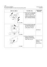
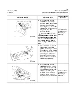
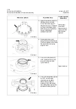
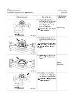
5. Wipe clean the mounting
surfaces of front output
flange of gear box and inter-
mediate drive shaft flange,
and install the intermediate
drive shaft to the front output
flange bolts of gear box,
screw in the locknut and
tighten it with a torque of
200±15Nm\ 147.5±11.06
lbf•ft.
21# wrench or
open-end 21#
fixed torque
spanner
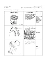
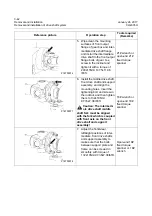
6. Install the middle drive shaft,
front drive shaft and support
assembly, and align the
mounting holes. Insert the
tightening bolt and screw in
the locknut, and then tighten
them to 132±10Nm\
97.35±7.38 lbf•ft.
Caution: The intermedi-
ate drive shaft middle
shaft fork must be aligned
with the fork which is coupled
with front axle on the front
drive shaft and support
assembly!
18# wrench or
open-end 18#
fixed torque
spanner
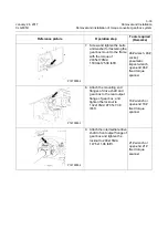
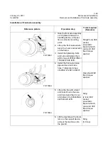
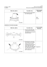
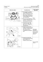
7. Adjust the front&rear,
left&right positions of inter-
mediate, front drive shafts
and support assembly to
make sure that the bolts
between support plate and
frame can be screwed in
smoothly with torque of
132±10Nm\ 97.35±7.38lbf•ft.
Open-end 18#
fixed torque
spanner or 18#
wrench
Reference picture
Operation step
Tools required
(Remarks)
P18T00076
P18T00077
P18T00078
Summary of Contents for CLG835H
Page 2: ......
Page 4: ...Contents January 24 2017 CLG835H...
Page 6: ...1 2 General Information January 24 2017 CLG835H...
Page 38: ...1 34 Machine Inspection Table January 24 2017 CLG835H...
Page 156: ...3 2 Power Train System January 24 2017 CLG835H...
Page 214: ...3 2 Power Train System January 24 2017 CLG835H...
Page 272: ...3 60 Testing and adjustment January 24 2017 Power Train Test CLG835H...
Page 276: ...4 4 Hydraulic System January 24 2017 CLG835H...
Page 552: ...6 2 Driver s Cab System January 24 2017 CLG835H...
Page 608: ...7 2 Structure January 24 2017 CLG835H...
Page 662: ...8 4 Electrical System January 24 2017 CLG835H...
Page 677: ...8 19 January 24 2017 Structure Function Principle CLG835H Power System P18E00014...

