2-56
Removal and Installation
January 24, 2017
Removal and installation of diesel engine
CLG835H
Installation
Figures
Contents
Tools
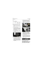
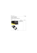
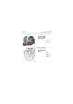
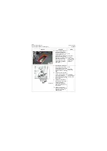
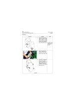
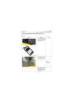
1. Install engine mounting sup-
port on engine with captive
bolt for engine mounting
support, and pre-tighten
captive bolt with an open-
end wrench.
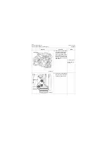
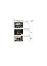
2. Tighten mounting base cap-
tive bolt of engine with a
torque wrench to torque of
120±50N.m (12±5kgf.m).
Tool:
Open-end
wrench 16#,
torque wrench
120±6N.m(12±0.
6kgf.m)
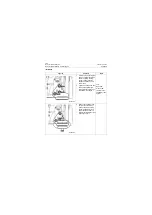
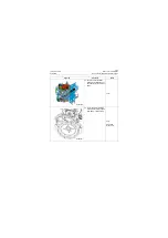
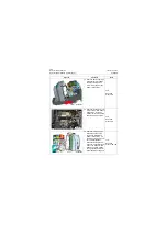
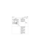
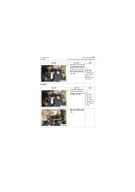
3. Place shock absorber and
cover at upper and lower
sides of engine mounting
support respectively, and
adjust shock absorber so
that it is installed into hole of
mounting support.
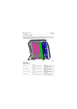
P18P00074
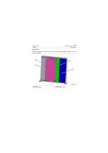
P18P00075
Summary of Contents for CLG835H
Page 2: ......
Page 4: ...Contents January 24 2017 CLG835H...
Page 6: ...1 2 General Information January 24 2017 CLG835H...
Page 38: ...1 34 Machine Inspection Table January 24 2017 CLG835H...
Page 156: ...3 2 Power Train System January 24 2017 CLG835H...
Page 214: ...3 2 Power Train System January 24 2017 CLG835H...
Page 272: ...3 60 Testing and adjustment January 24 2017 Power Train Test CLG835H...
Page 276: ...4 4 Hydraulic System January 24 2017 CLG835H...
Page 552: ...6 2 Driver s Cab System January 24 2017 CLG835H...
Page 608: ...7 2 Structure January 24 2017 CLG835H...
Page 662: ...8 4 Electrical System January 24 2017 CLG835H...
Page 677: ...8 19 January 24 2017 Structure Function Principle CLG835H Power System P18E00014...

