3-26
Removal and Installation
January 24, 2017
Removal and installation of torque converter-gearbox system
CLG835H
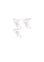
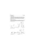
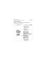
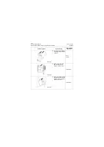
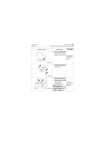
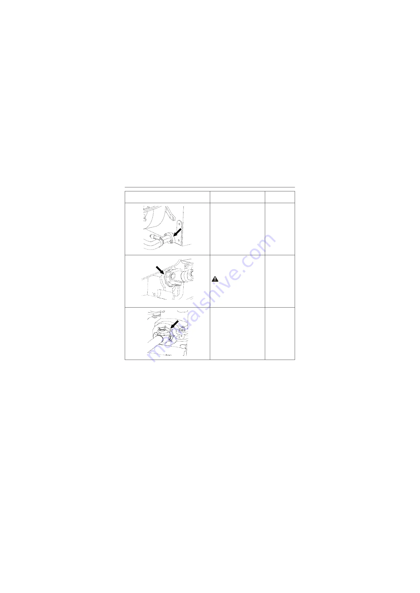
8. Remove the clamping bolt
fixing the oil filler steel-pipe
with a wrench.
10# Wrench
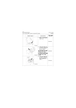
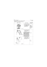
9. Remove the coupling lock-
nut between rear drive shaft
and rear output flange of
gear box assembly.
Caution: The drive shaft
assembly is composed
of slidable spline sleeve,
please take care to avoid per-
sonal injury caused by falling
of slide shaft fork during
removal.
18# Wrench
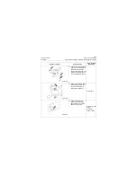
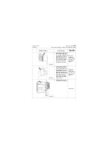
10. Remove the coupling lock-
nut between intermediate
drive shaft and front output
flange of transmission
assembly.
21# Wrench
Reference picture
Operation step
Tools required
(Remarks)
P18T00036
P18T00037
P18T00038
Summary of Contents for CLG835H
Page 2: ......
Page 4: ...Contents January 24 2017 CLG835H...
Page 6: ...1 2 General Information January 24 2017 CLG835H...
Page 38: ...1 34 Machine Inspection Table January 24 2017 CLG835H...
Page 156: ...3 2 Power Train System January 24 2017 CLG835H...
Page 214: ...3 2 Power Train System January 24 2017 CLG835H...
Page 272: ...3 60 Testing and adjustment January 24 2017 Power Train Test CLG835H...
Page 276: ...4 4 Hydraulic System January 24 2017 CLG835H...
Page 552: ...6 2 Driver s Cab System January 24 2017 CLG835H...
Page 608: ...7 2 Structure January 24 2017 CLG835H...
Page 662: ...8 4 Electrical System January 24 2017 CLG835H...
Page 677: ...8 19 January 24 2017 Structure Function Principle CLG835H Power System P18E00014...

