4-56
Structure Function Principle
January 24, 2017
Brake system
CLG835H
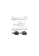
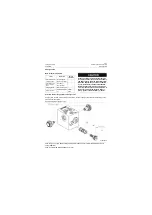
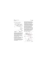
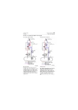
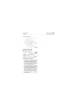
Main structure of brake valve is as shown in the
Figure above
, P1 port and P2 port are
connected with accumulator BR1&BR2
respectively, F1 port and F2 port are connected
with wheel brake of front and rear axle.
1) When the brake valve pedal is released, P1
port and P2 port are disconnected with F1
port and F2 port respectively, F1 port and F2
port are connected with T port and thus the
machine is under non-brake state.
2) With the brake valve pedal depressed, F1
port and F2 port is disconnected with T port,
and then P1 port is connected with A1 port,
P2 port is connected with A2 port, high pres-
sure oil stored in accumulator BR1 & BR2
enters into the wheel brake of front and rear
axle to apply brake, at the same time, the
brake switch acts and the brake light is on.
Two circuits of dual-circuit are independent
from each other, as one brake circuit is
faulty, the other circuit can still work nor-
mally.
Under brake, output oil pressure of brake valve is
proportional to brake pedal travel and force
applied on the brake pedal. When the brake
pedal is under static state (high-mounted
position), the output pressure (F1 port and F2
port) is zero and the brake valve cavity is
connected to oil tank (F1 and F2 are connected
to T). When the brake is depressed, output
pressure (F1 and F2) increases in proportional
relation with angular displacement of brake
pedal. When the brake pedal is depressed
completely, output pressure (F1 port and F2 port)
is limited to presetting pressure of valve and is
not related with oil supply pressure.
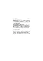
Precautions for use and maintenance of
brake valve
1. Be sure the connecting pipeline is clean,
without any impurities;
2. Periodically check the connection and fasten-
ing condition of all parts and tighten timely if
there is looseness;
3. Periodically check the working condition of
pedal: whether it is stuck when depressing
the pedal and whether it can return rapidly at
the time release;
4. If it is necessary to remove and clean brake
valve, do not clean seal ring, valve and other
rubber parts using brake fluid, kerosene and
other fluids which can corrode the rubber
parts, they can only be wiped by blowing or
clean cloth. Apply 3# lithium lubricating
grease on the moving parts, such as valve
and piston after being cleaned;
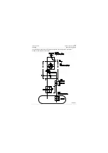
Hydraulic schematic of brake valve
P18H00043
Summary of Contents for CLG835H
Page 2: ......
Page 4: ...Contents January 24 2017 CLG835H...
Page 6: ...1 2 General Information January 24 2017 CLG835H...
Page 38: ...1 34 Machine Inspection Table January 24 2017 CLG835H...
Page 156: ...3 2 Power Train System January 24 2017 CLG835H...
Page 214: ...3 2 Power Train System January 24 2017 CLG835H...
Page 272: ...3 60 Testing and adjustment January 24 2017 Power Train Test CLG835H...
Page 276: ...4 4 Hydraulic System January 24 2017 CLG835H...
Page 552: ...6 2 Driver s Cab System January 24 2017 CLG835H...
Page 608: ...7 2 Structure January 24 2017 CLG835H...
Page 662: ...8 4 Electrical System January 24 2017 CLG835H...
Page 677: ...8 19 January 24 2017 Structure Function Principle CLG835H Power System P18E00014...


