rev. 11/1/2016
CB-PMPS, manual.doc
Copyright 2016 Vestil Manufacturing Corp. Page 1 of 23
CB-PMPS Series Counterbalanced Pallet Handlers
Instruction Manual
Receiving Instructions:
After delivery, IMMEDIATELY remove the packaging from the product. Inspect the product closely to determine
whether it sustained damage during transport.
If damage is discovered, immediately
record a complete
description of the damage on the bill of lading
. If the product is undamaged, discard the packaging.
NOTE:
Compliance with laws, regulations, codes, and non-voluntary standards enforced in the location where the product
is
used
is exclusively the responsibility of the end-user.
V
ESTIL
M
ANUFACTURING
C
ORP
.
2999 North Wayne Street, P.O. Box 507, Angola, IN 46703
Telephone: (260) 665-7586 -or- Toll Free (800) 348-0868
Fax: (260) 665-1339
www.vestilmfg.com
e-mail:
Table of Contents
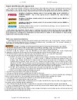
Hazard identification with signal words………………...…………………………………………………………………………........... 2
Safe Use Recommendations……………………………………………………………………………………………………………… 2
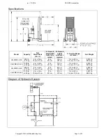
Product specifications by model……………………..……………………………………………………………………………………. 3
Diagram of Hydraulic System……………………………………………………………………………………………………………… 3
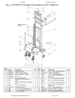
FIG. 1: CB-PMPS-6-50 exploded parts diagram & parts list………………………………………………….................................... 4
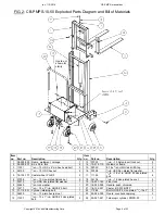
FIG. 2: CB-PMPS-10-50 exploded parts diagram & parts list…………………………………………………………………………. 5
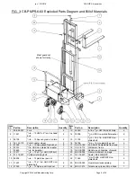
FIG. 3: CB-PMPS-6-60 exploded parts diagram & parts list…………………………………………………………………………… 6
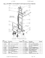
FIG. 4: CB-PMPS-10-50 exploded parts diagram & parts list…………………………………………………………………………. 7
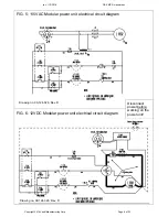
FIG. 5: 115VAC modular power unit electrical circuit diagram……..………………………...……………………………………….. 8
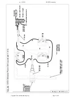
FIG. 6: 12VDC modular power unit electrical circuit diagram……………………..…………………………………………………... 8
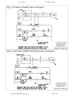
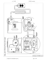
FIG. 7: Three phase AC modular power unit diagram………………………………………………………………………………….. 9
FIG. 8: Single phase 208 / 230 VAC modular power unit diagram…………………….………………………………………........... 9
FIGS. 9A & 9B: 12VDC modular power unit layout (parts 1 & 2)………………………..……………………..……………………... 10-11
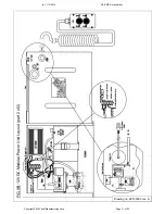
FIG. 10: AC modular power unit layout……………………………………………………………..……………………………………. 12
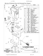
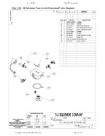
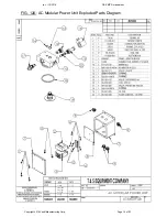
FIGS. 11A & 11B: DC modular power unit exploded parts diagram………………………………………………………………….. 13-14
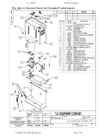
FIGS. 12A & 12B: AC modular power unit exploded parts diagram…………………………………………………………………... 15-16
Loading Instructions………………………………………………………………………………………………………………………… 17
Hydraulic system……………………………………………………………………………………………………………………………. 17-18
DC-Powered hydraulic system troubleshooting guide………………………………………………………………………………….. 18-19
Battery charger operation………………………………………………………………………………………………………………….. 20
Inspections & Maintenance……………………………………………………………....................................................................... 21-22
Labeling diagram…………..……………………………………………………………………………………………………………….. 22
Limited warranty…………………………………………………………………………………………………………………………….. 23


