background image

Garmin G1000 NXi Pilot’s Guide for the Cessna NAV III

190-02177-02  Rev. A

SY

STEM

O

VER

VIEW

FLIGHT

INSTRUMENTS

EIS

AUDIO P

ANEL

& CNS

FLIGHT

MANA

GEMENT

HAZARD

AV

OID

ANCE

AFCS

ADDITIONAL FEA

TURES

APPENDICES

INDEX

252

HAZARD AVOIDANCE

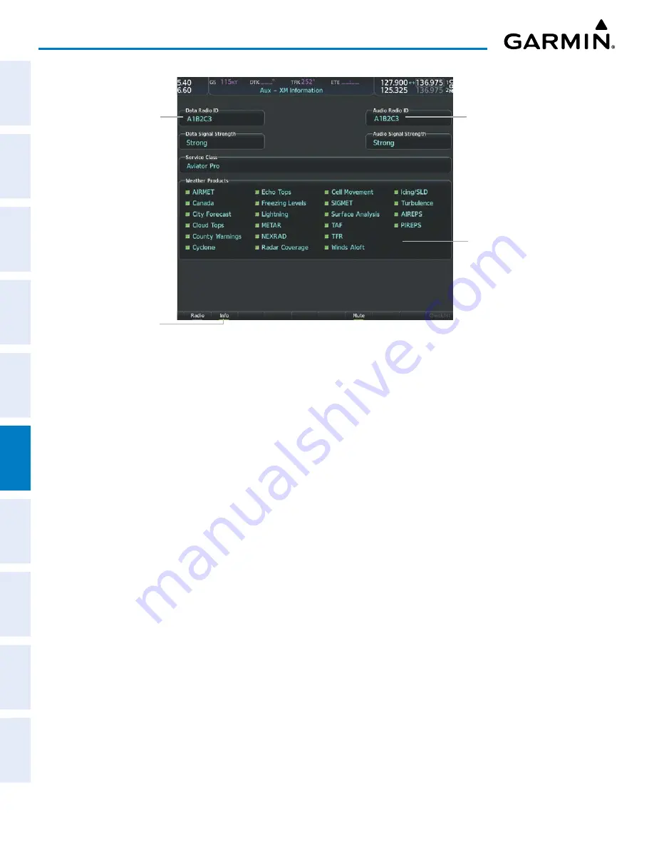
Figure 6-1  ‘Aux - XM Information’ Page

Data Radio ID 

(for SiriusXM 

Weather

Audio Radio ID 

(for SiriusXM Satellite 

Radio)

Weather Products 

(Available Products for 

Service Class Indicated in 

Green)

Press to Display ‘Aux - 

XM Information’ page

ACTIVATING GARMIN CONNEXT WEATHER

The Garmin Connext weather service requires an active Iridium satellite telephone and 

weather data subscription.  Registration begins by first obtaining the serial number(s) for the 
installed Iridium Satellite Transceiver (GSR 1), and the System ID.  Then go to the website 


flygarmin.com and follow the instructions for establishing an account for Garmin Connext data services.  
Note additional information about the airframe may be required.  After an account has been established, 
Garmin provides an access code that must be entered on the system and successfully transmitted to the 
Garmin Connext service via the Iridium satellite network.

Obtaining the LRU serial numbers and System ID:

1) 

Select the ‘Aux - System Status’ Page.

2) 

Press the

 LRU

 Softkey.

3) 

Turn the 

FMS

 Knob to scroll the cursor until ‘GSR 1’ is visible in the ‘LRU Information’ window.

4) 

Note the serial number displayed for ‘GSR 1’.

5) 

Push the 

FMS

 Knob to deactivate the cursor.

Summary of Contents for G1000 NXi

Page 1: ...OR 97302 U S A Garmin Europe Ltd Liberty House Hounsdown Business Park Southampton Hampshire SO40 9LR U K Garmin Corporation No 68 Zhangshu 2nd Road Xizhi District New Taipei City Taiwan Contact Garmin Product Support or view warranty information at flygarmin com Cessna Nav III Cessna Nav III System Software Version 2501 09 or later G1000 Pilot s Guide ...

Page 2: ......

Page 3: ...SYSTEM OVERVIEW FLIGHT INSTRUMENTS EIS AUDIO PANEL CNS FLIGHT MANAGEMENT HAZARD AVOIDANCE AFCS ADDITIONAL FEATURES APPENDICES INDEX ...

Page 4: ......

Page 5: ...and SafeTaxi are registered trademarks of Garmin International Inc or its subsidiaries Garmin ESP Garmin SVT Garmin Pilot SurfaceWatch and WireAware are trademarks of Garmin International Inc or its subsidiaries These trademarks may not be used without the express permission of Garmin Stormscope is registered trademarks of L 3 Communications CO Guardian is a trademark of CO Guardian Inc AC U KWIK ...

Page 6: ...anizations do not warrant or make any representations regarding its accuracy reliability or otherwise Licensee agrees not to sue AC U KWIK Organizations and to the maximum extent allowed by law to release and hold harmless AC U KWIK Organizations from any cause of action claims or losses related to any actual or alleged inaccuracies in the information arising out of Garmin s use of the information...

Page 7: ... weather Information contained within data link weather products may not accurately depict current weather conditions WARNING Do not use the indicated data link weather product age to determine the age of the weather informationshownbythedatalinkweatherproduct Duetotimedelaysinherentingatheringandprocessing weather data for data link transmission the weather information shown by the data link weat...

Page 8: ...detection system display as the sole basis for hazardousweatheravoidance Rangelimitationsandinterferencemaycausethesystemtodisplayinaccurate or incomplete information Refer to documentation from the lightning detection system manufacturer for detailed information about the system WARNING Do not rely solely upon the display of traffic information for collision avoidance maneuvering The traffic disp...

Page 9: ...f all GPS equipment Portions of the system use GPS as a precision electronic NAVigation AID NAVAID Therefore as with all NAVAIDs information presented by the system can be misused or misinterpreted and therefore become unsafe NOTE This device complies with part 15 of the FCC Rules Operation is subject to the following two conditions 1 this device may not cause harmful interference and 2 this devic...

Page 10: ... s responsibility to operate in accordance with established pertinent aircraft documents and regulatory guidance or limitations as applicable to the pilot the aircraft and installed equipment NOTE If the pilot operator wants or needs to adjust the database contact Garmin Product Support NOTE Garmin requests the flight crew report any observed discrepancies related to database information These dis...

Page 11: ...partial symbol NOTE When using Stormscope there are several atmospheric phenomena in addition to nearby thunderstorms that can cause isolated discharge points in the strike display mode However clusters of two or more discharge points in the strike display mode do indicate thunderstorm activity if these points reappear after the screen has been cleared NOTE ESP is designed to discourage exceeding ...

Page 12: ...Garmin G1000 NXi Pilot s Guide for the Cessna NAV III 190 02177 02 Rev A vi WARNINGS CAUTIONS AND NOTES Blank Page ...

Page 13: ...armin and or its third party providers You acknowledge that the Software is the property of Garmin and or its third party providers and is protected under the United States of America copyright laws and international copyright treaties You further acknowledge that the structure organization and code of the Software are valuable trade secrets of Garmin and or its third party providers and that the ...

Page 14: ...Garmin G1000 NXi Pilot s Guide for the Cessna NAV III 190 02177 02 Rev A SOFTWARE LICENSE AGREEMENT viii Blank Page ...

Page 15: ... split screen description Added WireAware Added visual approaches Added Baro QFE Altimeter settings Added Connext Weather Updated Audio Panel Information Added Underspeed Protection Added Electronic Stability and Protection B October 2019 All Production release for the following updates Fixed clerical errors Added QFE Constraints description Revised Approaches description Added Transition to Appro...

Page 16: ...Garmin G1000 NXi Pilot s Guide for the Cessna NAV III 190 02177 02 Rev A x REVISION INFORMATION Blank Page ...

Page 17: ...ransition Alerts 79 BARO QFE Indications 80 Low Altitude Annunciation 80 Marker Beacon Annunciations 80 Minimum Altitude Alerting 81 2 5 Abnormal Operations 82 Abnormal GPS Conditions 82 Garmin SVT Troubleshooting 82 SVT in Reversionary Mode 83 Unusual Attitudes 83 SVT Unusual Attitudes 84 SECTION 3 ENGINE INDICATION SYSTEM 3 1 Engine Display 86 Engine Display 98 3 2 EIS Display Reversionary Mode ...

Page 18: ...ormal Operation 247 Dead Reckoning Mode 247 SECTION 6 HAZARD AVOIDANCE 6 1 Data Link Weather 250 Activating Data Link Weather Services 251 Weather Product Age 254 Displaying Data Link Weather Products 258 Connext Data Requests 267 Weather Product Overview 270 FIS B Weather Status 304 Abnormal Operations for Garmin Connext Weather 305 6 2 Stormscope Lightning Detection System 307 Using the Stormsco...

Page 19: ...iriusXM Satellite Radio Services 428 Using SiriusXM Radio 429 8 7 Satellite Telephone and SMS Messaging 432 Registering with Garmin Connext 432 Disable Enable Iridium Transceiver 432 Telephone Communication 433 Text Messaging SMS 440 8 8 Flight Data Logging 451 8 9 Connext Setup 452 8 10 Auxiliary Video Optional 454 Video Setup 454 Display Selection 454 Zoom Range 456 8 11 Electronic Stability Pro...

Page 20: ...Garmin G1000 NXi Pilot s Guide for the Cessna NAV III 190 02177 02 Rev A xiv TABLE OF CONTENTS Blank Page ...

Page 21: ...r Temperature OAT probe to provide pressure altitude airspeed vertical speed and OAT information to the system This unit also provides aircraft attitude and heading information via ARINC 429 to the PFD MFD and IAU The ADAHRS contains advanced sensors including accelerometers and rate sensors and interfaces with the Magnetometer to obtain magnetic field information and with the IAUs to obtain GPS i...

Page 22: ...nnext Weather and SMS functions Flight Stream 510 1 Optional The Flight Stream Wireless Transceiver provides wireless connectivity between a compatible tablet mobile device and the avionics system GPS ADAHRS ADS B traffic SiriusXM audio and weather data can then be shared with the mobile device and flight plans can be transferred to or from the mobile device Also database updates may be performed ...

Page 23: ...W 64W Integrated Avionics Unit VHF COM GPS SBAS VOR LOC G S Flight Director AFCS Mode Logic Servo Logic 2 GIA 63W 64W Integrated Avionics Unit VHF COM GPS SBAS VOR LOC G S Flight Director AFCS Mode Logic Servo Logic 2 GDU 1054B 1050 MFD GEA 71 71B Engine Airframe I F GTX 345R or GTX 335R 33 Transponder GSA 81 3 Servos GMU 44 Magnetometer GSU 75 ADAHRS GRS 77 AHRS GDC 74A Air Data Computer ELT Emer...

Page 24: ...STEM OVERVIEW 1 2 SYSTEM CONTROLS NOTE The Audio Panel GMA is described in the Audio Panel CNS section The system controls are located on the PFD and MFD bezels and audio panel The controls for the PFD and MFD are discussed within the following pages of this section PFD MFD CONTROLS Figure 1 2 PFD MFD Controls Only with Garmin AFCS 20 21 19 18 22 23 25 24 28 27 26 29 4 2 1 6 5 7 9 8 3 12 16 11 10 ...

Page 25: ...selected course provides course reference to the pilot side flight director when operating in Navigation and Approach modes 7 COM Knob Turn to tune COM transceiver standby frequencies large knob for MHz small for kHz Push to toggle cyan tuning box between COM1 and COM2 The selected COM green is controlled with the COM MIC Key Audio Panel 8 COM Frequency Transfer Key EMERG Transfers the standby and...

Page 26: ...all knob selects the hundreds In addition to providing the standard system altitude alert function selected altitude provides an altitude setting for the Altitude Capture Hold mode of the AFCS 18 AP Key Engages disengages the Autopilot and Flight Director in the default vertical and lateral modes 19 HDG Key Selects deselects the Heading Select mode 20 NAV Key Selects deselects the Navigation mode ...

Page 27: ...ore inserting the SD card The data card slots on the PFD and MFD use Secure Digital SD cards and are located on the top right portion of the display bezels Each display bezel is equipped with two SD card slots Inserting and Removing an SD card Insert the SD card in the SD card slot pushing the card in until the spring latch engages The front of the card should remain flush with the face of the dis...

Page 28: ... powering up the system test annunciations are displayed and key annunciator lights also become momentarily illuminated on the audio panel and the display bezels On the PFD the ADAHRS AHRS begins to initialize and displays ADAHRS AHRS ALIGN Remain Stationary All system annunciations should disappear typically within one minute of power on When the MFD powers on the MFD Power on Page displays the f...

Page 29: ... Section while the left portion of the MFD is dedicated to the Engine Indication System see the EIS Section Both displays offer control for COM and NAV frequency selection Figure 1 5 System Normal Operation REVERSIONARY MODE NOTE The system alerts the pilot when backup paths are utilized by the LRUs Refer to the Appendices for further information regarding system specific alerts In the event of a ...

Page 30: ... PFD SYSTEM ANNUNCIATIONS NOTE Upon power on certain windows remain invalid as system equipment begins to initialize All windows should be operational within one minute of power on If any window continues to remain flagged the system should be serviced by a Garmin authorized repair facility When an LRU or LRU function fails a large red X is typically displayed on windows associated with the failed...

Page 31: ...l Display system is not receiving airspeed input from the air data computer System Annunciation Comment Display system is not receiving vertical speed input from the air data computer Display system is not receiving valid heading input from the ADAHRS AHRS or magnetometer Display system is not receiving altitude input from the air data computer Display system is not receiving valid OAT information...

Page 32: ... the softkey label back to MFD1 DB MFD database information is displayed again in the database window The ANN Test Softkey when pressed causes an annunciation test tone to be played Viewing LRU Information 1 Use the FMS Knob to select the Aux System Status Page 2 To place the cursor in the LRU Info Box Press the LRU Softkey Or a Press the MENU Key b With the Select LRU Window highlighted press the...

Page 33: ...h Roll Invalid Heading ADAHRS no Mag no Air Data Yes No No ADAHRS coast on gyros until invalid No Yes No Invalid Pitch Roll Heading ADAHRS no Mag coast on gyros until invalid No No No Table 1 2 ADAHRS Operation AHRS OPERATION NOTE Refer to the Appendices for specific system message information In addition to using internal sensors the AHRS uses GPS information magnetic field data and air data to a...

Page 34: ...RS no Mag no Air Mode Heading Invalid Heading Invalid Attitude Heading Invalid Y E S Y E S Y E S N O N O N O Air Data Available and Reliable Mag Data Available and Reliable Y E S N O Mag Data AND Air Data Available and Reliable GPS Data Available and Reliable Figure 1 8 AHRS Operation GPS INPUT FAILURE NOTE In flight initialization ofADAHRS AHRS when operating without any valid source of GPS data ...

Page 35: ... be providing accurate data but one receiver may be providing a better GPS solution than the other In this case the GPS receiver producing the better solution is automatically coupled to the PFD GPS sensor annunciations are most often seen after system power on when one GPS receiver has acquired satellites before the other or one of the GPS receivers has not yet acquired a SBAS signal While the ai...

Page 36: ... containing the satellite identification number Satellites whose signals are currently being used are represented by solid ovals SATELLITE SIGNAL STATUS This Satellite Status Box provides information regarding signal status The accuracy of the aircraft s GPS fix is calculated using Estimated Position Uncertainty EPU Dilution of Precision DOP and horizontal and vertical figures of merit HFOM and VF...

Page 37: ...r Autonomous Integrity Monitoring RAIM is a GPS receiver function that performs a consistency check on all tracked satellites RAIM ensures the available satellite geometry allows the receiver to calculate a position within a specified RAIM protection limit 2 0 nautical miles for enroute and 0 3 nm for approaches During oceanic enroute and terminal phases of flight RAIM is available nearly 100 of t...

Page 38: ...t been computed for the current waypoint time and date combination Computing Availability RAIM calculation in progress RAIM Available RAIM is predicted to be available for the specified waypoint time and date RAIM not Available RAIM is predicted to be unavailable for the specified waypoint time and date Predicting RAIM availability at present position 1 Select the Aux GPS Status Page 2 If necessar...

Page 39: ...box 5 Push the FMS Knob to remove the cursor GPS SATELLITE SIGNAL STRENGTHS The Aux GPS Status Page can be helpful in troubleshooting weak or missing signal levels due to poor satellite coverage or installation problems As the GPS receiver locks onto satellites a signal strength bar is displayed for each satellite in view with the appropriate satellite ID number below each bar The progress of sate...

Page 40: ...management functions including GPS NAV terrain traffic and weather optional Each softkey sublevel has a Back Softkey which can be pressed to return to the previous level If messages remain after acknowledgement the Alerts Softkey is black on white The Alerts Softkey is visible in all softkey levels For the top level softkeys and the transponder XPDR levels the Ident Softkey remains visible The fol...

Page 41: ...ata source selection on the PFD Map LTNG Off Disables lightning function on PFD Map The softkey annunciator is green when the lightning function is off Datalink Selects the datalink weather source for the PFD Map STRMSCP Adds or removes the display of Stormscope information on the PFD Map The softkey annunciator is green when the function is on When the function is off the annunciator is gray TFC ...

Page 42: ...ing tuning and selection of the DME optional XPDR Displays the transponder selection softkeys Standby Selects transponder Standby Mode transponder does not reply to any interrogations On Activates transponder transponder replies to identification interrogations ALT Altitude Reporting Mode transponder replies to identification and altitude interrogations VFR Automatically enters the VFR code 1200 i...

Page 43: ...re and temperature fuel calculations electrical system information and system softkeys RST Fuel Resets calculated fuel remaining to default and resets fuel used to zero GAL REM Press to display the fuel totalizer softkeys 10 GAL Press to decrease remaining fuel quantity in 10 gallon increments 1 GAL Press to decrease remaining fuel quantity in 1 gallon increments 1 GAL Press to increase remaining ...

Page 44: ... features visible Detail 3 Declutters land data Detail 2 Declutters land and SUA data Detail 1 Removes everything except for the active flight plan Charts When available displays optional airport and terminal procedure charts CHRT Opt Displays chart display settings softkeys if available ROT CCW Rotates chart 90 degrees counter clockwise ROT CW Rotates chart 90 degrees clockwise Fit WDTH Chart zoo...

Page 45: ...and review options Menus display No Options when there are no options for the window page selected The main controls used in association with all window page group operations are described in Section 1 2 Softkey selection does not display menus or submenus Navigating the Page Menu Window 1 Press the MENU Key to display the Page Menu Window 2 Turn the FMS Knob to scroll through a list of available ...

Page 46: ...irport Procedures Weather Information XM Procedure Loading the active title of the page changes while the page name in the list remains the same Figure 1 12 Page Title and Page Groups Page Group Active Page Title MFD Page Groups Pages in Current Group The main page groups are navigated using the FMS Knob specific pages within each group can vary depending on the configuration of optional equipment...

Page 47: ...formation Aux Auxiliary Trip Planning Utility GPS Status System Setup 1 2 XM Radio Pages optional XM Information Info Softkey XM Radio Radio Softkey Satellite Phone optional Telephone Phone Softkey Text Messaging SMS Softkey System Status Video optional ADS B Status Connext Setup Databases FPL Flight Plan Active Flight Plan Wide View Narrow View View Softkey Flight Plan Catalog Stored Flight Plan ...

Page 48: ... from the FPL Active Flight Plan Page the page title will change to show FPL Chart Active Flight Plan Figure 1 13 Split Screen Mode MFD in Split Screen Mode Narrow View Cyan Pane Selector shows Charts is the active display pane Page Title shows Map Chart Navigation Map Softkeys for the active display pane CONTROLLING DISPLAY PANES In split screen mode the active display pane is outlined by a cyan ...

Page 49: ...ight Plan Page press the Charts Softkey or press the MENU Key and select Chart Mode On If necessary press the CHRT Opt Softkey and press the Full SCN Softkey to disable full screen mode 2 To disable the split screen mode press the Charts Softkey again or press the MENU Key and select Chart Mode Off The display returns to the base page either the Map Navigation Map Page or the FPL Active Flight Pla...

Page 50: ... Setup 2 DATE TIME The system obtains the current Universal Coordinated Time UTC date and time directly from the GPS satellite signals shown on the Aux GPS Status Page System time displayed in the lower right corner of the PFD can be displayed in three formats local 12 hr local 24 hr or UTC Local time is set by adding subtracting an offset hours minutes to from UTC Figure 1 16 System Time UTC Form...

Page 51: ... distances Map ranges DIS GS TAS XTK Fields Navigation Data Bar All distances on MFD Altitude buffer distance System Setup Arrival Alert trigger distance System Setup All speeds on MFD Altitude and Vertical Speed Feet Meters All altitudes on MFD All elevations on MFD Temperature Celsius Fahrenheit All temperatures on PFD Total Air Temperature Trip Planning Page Fuel and Fuel Flow Gallons Fuel para...

Page 52: ...rspace Alerts settings ARRIVAL ALERTS See the Flight Management Section for information on Arrival Alerts settings SURFACEWATCH See the Additional Features Section for information on SurfaceWatch settings FLIGHT DIRECTOR The Flight Director command bars format is set to Single Cue and may not be changed See the AFCS Section for more information BARO QFE See the Flight Instruments Section for infor...

Page 53: ...rner of the MFD The timeout can range from two to ten seconds Selecting page navigation settings 1 Use the FMS Knob to select the Aux System Setup 2 Page 2 Push the FMS Knob momentarily to activate the flashing cursor 3 Turn the large FMS Knob to highlight the Change On 1st Click field in the Page Navigation Box 4 Turn the small FMS Knob to select Off or On 5 Turn the large FMS Knob to highlight t...

Page 54: ...ayed from the time of the last reset Figure 1 17 Aux Utility Page TIMERS The system timers available on the Aux Utility Page include Stopwatch like generic timers Total time in flight timer Time since departure The generic timer can be set to count up or down from a specified time HH MM SS When the countdown on the timer reaches zero the digits begin to count up from zero If the timer is reset bef...

Page 55: ...the flashing cursor 3 Turn the large FMS Knob to highlight the field next to the flight timer 4 Turn the small FMS Knob to select the starting criterion Pwr On or In Air and press the ENT Key Resetting the flight timer 1 Use the FMS Knob to select the Aux Utility Page 2 Press the MENU Key 3 With Reset Flight Timer highlighted press the ENT Key The system records the time at which departure occurs ...

Page 56: ...ght the desired reset option and press the ENT Key The selected parameters are reset to zero and begin to display data from the point of reset SCHEDULER The system s Scheduler feature can be used to enter and display reminder messages e g Switch fuel tanks Overhaul etc in the Alerts Window on the PFD Messages can be set to display based on a specific date and time event once the message timer reac...

Page 57: ...ting Periodic Message issued each time the message timer reaches zero 7 Press the ENT Key again or use the large FMS Knob to move the cursor to the next field 8 For periodic and one time message use the FMS Knob to enter the timer value HHH MM SS from which to countdown and press the ENT Key 9 For event based messages a Use the FMS Knob to enter the desired date DD MMM YY and press the ENT Key b P...

Page 58: ...Auto is now highlighted next to PFD Display If desired turn the large FMS Knob to select Auto next to MFD Display 2 Turn the small FMS Knob to select Manual and press the ENT Key The intensity value is now highlighted 3 Use the FMS Knob to enter the desired backlighting then press the ENT Key 4 To remove the menu press the CLR or MENU Key Adjusting key backlighting 1 Press the PFD MENU Key to disp...

Page 59: ...re also presented on the PFD and are explained in other sections of this Pilot s Guide The following flight instruments and supplemental flight data are displayed on the PFD Airspeed Indicator showing Indicated Airspeed True Airspeed Airspeed awareness ranges Vspeed reference bugs Attitude Indicator with slip skid indication Altimeter showing Trend vector Barometric setting Selected altitude Verti...

Page 60: ... Airspeed Indicator 2 True Airspeed 3 Current Heading 4 Horizontal Situation Indicator HSI 5 Outside Air Temperature OAT 6 Softkeys 7 System Time 8 Generic Timer 9 Transponder Data Box 10 Selected Heading Bug 11 Barometric Altimeter Setting 12 Turn Rate Indicator 13 Vertical Speed Indicator VSI 14 Selected Altitude Bug 15 Altimeter 16 Selected Altitude 17 Navigation Status Box 18 Slip Skid Indicat...

Page 61: ...L CNS FLIGHT MANAGEMENT HAZARD AVOIDANCE AFCS ADDITIONAL FEATURES APPENDICES INDEX Figure 2 2 Additional PFD Information 1 Selected Heading 2 Wind Data Box 3 Inset Map 4 Bearing Information Windows 5 Minimum Altitude Alert 6 Desired Track 7 Required Vertical Speed Indicator 8 Vertical Deviation Indication 9 VNV Target Altitude 1 3 2 5 4 6 7 8 9 ...

Page 62: ...n 20 below to 20 above the horizon line minor pitch marks occur every 2 5 When the optional Garmin Synthetic Vision System Technology system Garmin SVT is activated the pitch scale is reduced to 10 up and 7 5 down refer to the Additional Features section for more information about Synthetic Vision The inverted white triangle indicates zero on the roll scale Major tick marks at 30 and 60 and minor ...

Page 63: ...speed awareness range a flaps operating range normal operating range caution range and never exceed speed VNE Speeds above the never exceed speed VNE appear in the high speed warning range represented on the airspeed tape by red white barber pole coloration The Airspeed Trend Vector is a vertical magenta line that appears to the right of the color coded speed range strip when airspeed is either ac...

Page 64: ...mall FMS Knob clockwise to On or counterclockwise to Off 6 To remove the window press the CLR Key or the TMR REF Softkey Figure 2 7 References Window and Menu References Window References Menu The pilot can also enable disable all Vspeed Reference Bugs as a group Enabling disabling Vspeed Reference Bugs as a group or restoring all default settings 1 Press the TMR REF Softkey 2 Press the MENU Key 3...

Page 65: ...r down the left of the altitude tape with the end resting at the approximate altitude to be reached in six seconds at the current vertical speed The trend vector is not shown if altitude remains constant or if data needed for calculation is not available due to a system failure Setting the Selected Altitude Turn the ALT Knob to set the Selected Altitude Turn the large knob for 1000 ft increments s...

Page 66: ...descent path If the change is made while nearing a waypoint with a VNV Target Altitude the aircraft may not re establish on the descent path in time to meet the vertical constraint NOTE Changing the BARO setting with the autopilot engaged in ALT mode will result in the aircraft slowly climbing or descending to return to the original indicated altitude Selecting the altimeter barometric pressure se...

Page 67: ...gin is the current reference Therefore while QFE is active and the QFE reference is the origin QFE constraints cannot be entered for the destination airport runway QFE constraints cannot be entered for any arrival approach waypoints Entering an MSL AGL constraint for any departure enroute waypoints displays a message clarifying the constraint will be shown as a converted QFE value relative to the ...

Page 68: ...scale with labels at 1000 and 2000 fpm 5 and 10 mps and minor tick marks every 500 fpm 2 5 mps Digits appear in the pointer when the climb or descent rate is greater than 100 fpm 0 5 mps If the rate of ascent descent exceeds 2000 fpm 10 mps the pointer appears at the edge of the tape and the rate appears inside the pointer A magenta chevron is displayed on the VSI to indicate the Required Vertical...

Page 69: ...ecomes the active waypoint and GPS is the selected navigation source Full scale deflection two dots is angular with upper and lower limits The upper limit is 492 feet 150 meters and lower limits depend on approach service level LNAV VNAV LNAV V LP V is 148 feet 45 meters LPV is 49 feet 15 meters If the approach downgrades past the final approach fix FAF NO GP is displayed in place of the diamond N...

Page 70: ...aircraft is outside of SBAS coverage SBAS is manually disabled on the Aux GPS Status Page Baro VNAV is also the source of vertical approach guidance if the LNAV VNAV procedure does not support SBAS vertical guidance Garmin s Baro VNAV system is automatically temperature compensated for the final approach segment In context of GPS LNAV VNAV approaches the system generated GlidePath is automatically...

Page 71: ...ical Deviation Limit Indicators Excessive deviation VERTICAL NAVIGATION VNV INDICATIONS When a VNV flight plan has been activated VNV indications VNV Target Altitude RVSI VDI appear on the PFD in conjunction with the TOD within 1 minute message and Vertical track voice alert See the Flight Management and AFCS sections for details on VNV features VNV indications are removed from the PFD according t...

Page 72: ...pass card in a heading up orientation Letters indicate the cardinal points with numeric labels every 30 Long dashes are at 10 intervals and short dashes are at 5 intervals A digital reading of the current heading appears on top of the HSI The HSI also presents turn rate course deviation bearing and selected navigation source information The HSI is available in two formats a 360 compass rose and a ...

Page 73: ...ding 15 Turn Rate and Heading Trend Vector 16 Selected Heading 6 1 3 5 7 16 13 12 2 8 10 11 15 14 4 9 Figure 2 16 Horizontal Situation Indicator The HSI Map is a 210 expanded compass rose which also includes a navigation map with overlay capabilities such as topographical weather and land information The HSI Map contains a Course Pointer a combined To From Indicator with a sliding deviation indica...

Page 74: ...e is not active The Selected Course CRS is shown to the upper right of the HSI when the selected navigation source is VOR or LOC and in magenta when the selected navigation source is GPS with OBS Mode active Adjusting the Selected Heading Turn the HDG Knob to set the Selected Heading Push the HDG Knob to synchronize the bug to the current heading Adjusting the Selected Course Turn the CRS Knob to ...

Page 75: ...d of the trend vector gives the heading predicted in six seconds based on the present turn rate A standard rate turn is shown on the indicator by the trend vector stopping at the standard turn rate tick mark corresponding to a predicted heading of 18 from the current heading At rates greater than 4 deg sec an arrowhead appears at the end of the magenta trend vector and the prediction is no longer ...

Page 76: ... ILS frequency the bearing source and the bearing pointer is removed from the HSI When NAV1 or NAV2 is the selected bearing source the frequency is replaced by the station identifier when the station is within range If GPS is the bearing source the active waypoint identifier is displayed instead of a frequency The bearing pointer is removed from the HSI and dashes are displayed in the information ...

Page 77: ... Window press the DME Softkey again COURSE DEVIATION INDICATOR CDI The deviation bar D bar within the Course Deviation Indicator CDI moves left or right from the course pointer along a lateral deviation scale to display aircraft position relative to the course If the course deviation data is not valid the D bar is not displayed Figure 2 22 Course Deviation Indicator Deviation bar Flight Phase Cros...

Page 78: ...e cyan tuning box over the NAV2 standby frequency 3 Press the CDI Softkey a third time to return to GPS Figure 2 24 Selecting a Navigation Source Pressing the CDI Softkey Cycles through Navigation Sources GPS Selected NAV1 Selected for Tuning LOC1 Selected NAV2 Selected for Tuning VOR2 Selected The system automatically changes from GPS to LOC navigation source and changes the CDI scaling according...

Page 79: ...int GPS CDI SCALING When GPS is the selected navigation source the flight plan legs are sequenced automatically and annunciations appear on the HSI for the flight phase Flight phase annunciations are normally shown in magenta but when cautionary conditions exist the color changes to amber If the current leg in the flight plan is a heading leg HDG LEG is annunciated in magenta beneath the aircraft ...

Page 80: ...rocedure the flight phase and CDI scale does not change until the aircraft arrives at the last departure waypoint if more than 30 nm from the departure airport or the leg after the last departure waypoint has been activated or a direct to waypoint is activated If after completing the departure procedure the nearest airport is more than 200 nm away from the aircraft and the approach procedure has n...

Page 81: ...witches back to terminal mode under the following conditions The next leg in the missed approach procedure is not aligned with the final approach path The next leg in the missed approach procedure is not a CA CD CF CI CR DF FA FC FD FM IF or TF After any leg in the missed approach procedure that is not a CA or FA Flight Phase Annunciation Automatic CDI Full scale Deflection Departure DPRT 0 3 nm T...

Page 82: ...is disabled the GPS flight plan returns to normal operation with automatic sequencing of waypoints following the course set in OBS Mode The flight plan on the moving map retains the modified course line Figure 2 29 Omni bearing Selector OBS Mode GPS Selected Pressing the OBS Softkey Enables OBS Mode OBS Mode Enabled Extended Course Line Pressing the OBS Softkey Again Disables OBS Mode Enabling dis...

Page 83: ...the Cessna NAV III 63 FLIGHT INSTRUMENTS SYSTEM OVERVIEW FLIGHT INSTRUMENTS EIS AUDIO PANEL CNS FLIGHT MANAGEMENT HAZARD AVOIDANCE AFCS ADDITIONAL FEATURES APPENDICES INDEX Figure 2 30 Suspending Automatic Waypoint Sequencing SUSP Softkey SUSP Annunciation ...

Page 84: ...S Knob to enter the desired time 4 Press the ENT Key The Up Dn field is now highlighted 5 Turn the small FMS Knob to display the Up Dn Window 6 Turn the small FMS Knob to select Up or Dn 7 Press the ENT Key Start is now highlighted 8 Press the ENT Key to start the timer The field changes to Stop If the timer is counting down it will start counting up after reaching zero 9 To stop the timer press t...

Page 85: ... information is invalid or unavailable the window displays NO WIND DATA Wind data can be displayed in three different ways Figure 2 32 Wind Data Option 1 Option 2 Option 3 No Data Displaying wind data 1 Press the PFD Opt Softkey 2 Press the Wind Softkey to display wind data to the left of the HSI 3 Press one of the numbered option softkeys to change how wind data is displayed Option 1 Headwind tai...

Page 86: ...ry loss of the GPS signal will cause SVT to be disabled although the softkeys will still appear functional until the required data is restored The SVT terrain display shows land contours colors are consistent with those of the topographical map display large water features towers and other obstacles over 200 AGL that are included in the obstacle database Wire obstacles such as power lines may be a...

Page 87: ...ays Terrain HDG LBL APT Sign and Wire The Back Softkey returns to the previous level of softkeys Synthetic Terrain must be active before any other SVT feature may be activated Pathways HDG LBL and APT Sign Softkeys are only available when the Terrain Softkey is activated gray with black characters After activating the Terrain Softkey the Pathways HDG LBL and APT Sign softkeys may be activated in a...

Page 88: ...the terrain horizon is difficult to distinguish from other terrain being displayed It may not align with the terrain horizon particularly when the terrain is mountainous or when the aircraft is flown at high altitudes AIRPORT SIGNS Airport Signs provide a visual representation of airport location and identification on the synthetic terrain display When activated the signs appear on the display whe...

Page 89: ...ways available when the Synthetic Terrain feature is in operation The FPM represents the direction of the flight path as it relates to the terrain and obstacles on the display while the airplane symbol represents the aircraft heading The FPM works in conjunction with the Pathways feature to assist the pilot in maintaining desired altitudes and direction when navigating a flight plan When on course...

Page 90: ... the selected route of flight shown as colored rectangular boxes representing the horizontal and vertical flight path of the active flight plan The box size represents 700 feet wide by 200 feet tall during enroute oceanic and terminal flight phases During an approach the box width is 700 feet or one half full scale deviation on the HSI whichever is less The height is 200 feet or one half full scal...

Page 91: ...hen the selected navigation information is not available Pathways are not displayed beyond the active leg when leg sequencing is suspended and are not displayed on any portion of the flight plan leg that would lead to intercepting a leg in the wrong direction Departure and Enroute Prior to intercepting an active flight plan leg pathways are displayed as a series of boxes with pointers at each corn...

Page 92: ... glidepath or glideslope From the vertical path descent glidepath or glideslope intercept point the pathways are shown inbound to the Missed Approach Point MAP along the published lateral and vertical descent path or at the selected altitude whichever is lower During an ILS approach the initial approach segment is displayed in magenta at the segment altitudes if GPS is selected as the navigation s...

Page 93: ...he MAHP If the initial missed approach leg is defined by a course using other than GPS pathways are not displayed for that segment In this case the pathways displayed for the next leg may be outside the field of view and will be visible when the aircraft has turned in the direction of that leg Pathways are displayed along each segment including the path required to track course reversals that are ...

Page 94: ...wareness of runway location with respect to the surrounding terrain All runway thresholds are depicted at their respective elevations as defined in the database In some situations where threshold elevations differ significantly crossing runways may appear to be layered As runways are displayed those within 45 degrees of the aircraft heading are displayed in white Other runways will be gray in colo...

Page 95: ...nset map or MFD traffic page If the traffic altitude is unknown the traffic will not be displayed on the SVT display For more details refer to the traffic system discussion in the Hazard Avoidance section TERRAIN AND OBSTACLE ALERTING Terrain alerting on the synthetic terrain display is triggered by Forward looking Terrain Avoidance FLTA alerts from the Terrain SVT or optional TAWS system and corr...

Page 96: ...n 1000 feet below the aircraft altitude are not shown Obstacles may appear behind the flight instruments Figure 2 42 Obstacle Caution Potential Impact Obstacle Terrain Annunciation WIREAWARE POWER LINE OBSTACLES NOTE The WireAware obstacle database does not contain all known power lines And as such obstacle avoidance is the sole responsibility of the flight crew To enhance safety SVT incorporates ...

Page 97: ... on the MFD Map Navigation Map Page Two dashed lines forming a V shape in front of the aircraft symbol on the map represent the forward viewing area shown on the PFD Configuring SVT field of view depiction on the navigation map 1 While viewing the Map Navigation Map Page press the MENU Key to display the Page Menu 2 Turn the large FMS Knob to highlight Map Settings and press the ENT Key 3 Turn the...

Page 98: ...gure 2 44 Enabling SVT Field of View on the MFD Map Navigation Map Page Menu Map Settings Menu Map Group Field of View Option Field of View The following figure compares the PFD forward looking depiction with the MFD plan view and Field of View turned on Figure 2 45 PFD and MFD Field of View Comparison Lines Depict PFD Field of View SVT View on the PFD Field of View on the MFD Obstacle outside of ...

Page 99: ...0 ft BARO TRANSITION ALERTS The Baro Transition Alerts flash the barometric pressure setting to remind the pilot to change the barometric pressure setting to or from standard Two alerts are available The altitude Baro Transition Alert occurs when climbing through the transition altitude beginning at 200 feet below this altitude The flight level Baro Transition Alert occurs when descending through ...

Page 100: ...ARO QFE Mode Armed LOW ALTITUDE ANNUNCIATION NOTE The Low Altitude Annunciation requires SBAS Terrain alerts from Terrain SVT or TAWS B systems will appear instead of the Low Altitude Annunciation when these systems are operating and not inhibited When the Final Approach Fix FAF is the active waypoint in a GPS SBAS approach using vertical guidance a Low Altitude Annunciation may appear if the curr...

Page 101: ...ircraft reaches the alert altitude the bug and text turn amber and a Minimums Minimums voice alert is issued Figure 2 50 Barometric MDA DH Alerting Visual Annunciations Within 100 ft Altitude Reached Beyond 100 ft Barometric Minimum Bug Barometric Minimum Box Alerting is inhibited while the aircraft is on the ground and until the aircraft reaches 150 feet above the setting for the alert The functi...

Page 102: ...conds DR Lower left of aircraft symbol Dead Reckoning System is using projected position rather than GPS position to compute navigation data and sequence active flight plan waypoints Table 2 4 Abnormal GPS Conditions Annunciated on HSI Figure 2 52 Example HSI Annunciations In Dead Reckoning Mode the CDI is removed from the display when GPS is the selected navigation source Verify the following amb...

Page 103: ...e pitch The chevrons are displayed on the Attitude Indicator starting at 50 above and 30 below the horizon line If pitch exceeds 30 20 or bank exceeds 65 some information displayed on the PFD is removed The Altimeter and Airspeed Attitude Vertical Speed and Horizontal Situation indicators remain on the display and the Bearing Information Alerts and Annunciation windows can be displayed during such...

Page 104: ...TTITUDES During extreme pitch attitudes the display shows either a brown or blue colored bar at the top or bottom of the screen to represent earth or sky The blue colored bar is also displayed when terrain gradient is great enough to completely fill the display This is intended to prevent losing sight of the horizon during extreme pitch attitudes Figure 2 54 Blue Sky Bar with Full Display Terrain ...

Page 105: ...cation System EIS displays electrical fuel and engine information on the left side of the Multi Function Display MFD EIS information can also be expanded to view and access additional information and engine assist features by pressing the Engine Softkey Figure 3 1 MFD with EIS display EIS Display Green bands on the instruments indicate normal ranges of operation amber and red bands indicate cautio...

Page 106: ...A 86 ENGINE INDICATION SYSTEM SYSTEM OVERVIEW FLIGHT INSTRUMENTS EIS AUDIO PANEL CNS FLIGHT MANAGEMENT HAZARD AVOIDANCE AFCS ADDITIONAL FEATURES APPENDICES INDEX 3 1 ENGINE DISPLAY Engine System Display Engine Display 3 4 5 11 Figure 3 2 Model 172R 8 6 10 7 1 2 12 9 3 4 2 ...

Page 107: ...s Fahrenheit F 5 Exhaust Gas Temperature Indicator EGT Displays exhaust gas temperature in degrees Fahrenheit F 6 Vacuum Pressure Indicator VAC Displays standby vacuum pump pressure 7 Calculated Fuel Used GAL Used Displays fuel used in gallons based on fuel flow 8 Calculated Fuel Remaining GAL REM Displays the totalizer based fuel remaining in gallons 9 Fuel Quantity Indicator Fuel QTY GAL Display...

Page 108: ...77 02 Rev A 88 ENGINE INDICATION SYSTEM SYSTEM OVERVIEW FLIGHT INSTRUMENTS EIS AUDIO PANEL CNS FLIGHT MANAGEMENT HAZARD AVOIDANCE AFCS ADDITIONAL FEATURES APPENDICES INDEX Engine System Display Engine Display 3 4 5 11 Figure 3 3 Model 172S 8 6 10 7 1 2 12 9 3 4 2 ...

Page 109: ...s Fahrenheit F 5 Exhaust Gas Temperature Indicator EGT Displays exhaust gas temperature in degrees Fahrenheit F 6 Vacuum Pressure Indicator VAC Displays standby vacuum pump pressure 7 Calculated Fuel Used GAL Used Displays fuel used in gallons based on fuel flow 8 Calculated Fuel Remaining GAL REM Displays the totalizer based fuel remaining in gallons 9 Fuel Quantity Indicator Fuel QTY GAL Display...

Page 110: ...7 02 Rev A 90 ENGINE INDICATION SYSTEM SYSTEM OVERVIEW FLIGHT INSTRUMENTS EIS AUDIO PANEL CNS FLIGHT MANAGEMENT HAZARD AVOIDANCE AFCS ADDITIONAL FEATURES APPENDICES INDEX 3 4 5 11 8 10 1 2 12 Engine System Display Engine Display 7 14 13 Figure 3 4 Model 182T 6 9 3 ...

Page 111: ...renheit F 6 Engine Hour Indicator ENG HRS Displays a numeric indication for the time in hours hrs the engine has been in service 7 Vacuum Pressure Indicator VAC Displays standby vacuum pump pressure 8 Cylinder Head Temperature Indicator CHT Displays cylinder head temperature in degrees Fahrenheit F 9 Calculated Fuel Remaining GAL REM Displays the totalizer based fuel remaining in gallons 10 Calcul...

Page 112: ... 02 Rev A 92 ENGINE INDICATION SYSTEM SYSTEM OVERVIEW FLIGHT INSTRUMENTS EIS AUDIO PANEL CNS FLIGHT MANAGEMENT HAZARD AVOIDANCE AFCS ADDITIONAL FEATURES APPENDICES INDEX 3 4 5 11 8 10 1 2 12 Engine System Display Engine Display 7 14 13 Figure 3 5 Model T182T 6 9 3 ...

Page 113: ...nheit F 6 Engine Hour Indicator ENG HRS Displays a numeric indication for the time in hours hrs the engine has been in service 7 Vacuum Pressure Indicator VAC Displays standby vacuum pump pressure 8 Cylinder Head Temperature Indicator CHT Displays cylinder head temperature in degrees Fahrenheit F 9 Calculated Fuel Remaining GAL REM Displays the totalizer based fuel remaining in gallons 10 Calculat...

Page 114: ...7 02 Rev A 94 ENGINE INDICATION SYSTEM SYSTEM OVERVIEW FLIGHT INSTRUMENTS EIS AUDIO PANEL CNS FLIGHT MANAGEMENT HAZARD AVOIDANCE AFCS ADDITIONAL FEATURES APPENDICES INDEX 3 4 5 11 8 10 1 2 12 Engine System Display Engine Display 7 14 13 Figure 3 6 Model 206H 6 9 3 ...

Page 115: ...renheit F 6 Engine Hour Indicator ENG HRS Displays a numeric indication for the time in hours hrs the engine has been in service 7 Vacuum Pressure Indicator VAC Displays standby vacuum pump pressure 8 Cylinder Head Temperature Indicator CHT Displays cylinder head temperature in degrees Fahrenheit F 9 Calculated Fuel Remaining GAL REM Displays the totalizer based fuel remaining in gallons 10 Calcul...

Page 116: ... 02 Rev A 96 ENGINE INDICATION SYSTEM SYSTEM OVERVIEW FLIGHT INSTRUMENTS EIS AUDIO PANEL CNS FLIGHT MANAGEMENT HAZARD AVOIDANCE AFCS ADDITIONAL FEATURES APPENDICES INDEX 3 4 5 11 8 10 1 2 12 Engine System Display Engine Display 7 14 13 Figure 3 7 Model T206H 6 9 3 ...

Page 117: ...nheit F 6 Engine Hour Indicator ENG HRS Displays a numeric indication for the time in hours hrs the engine has been in service 7 Vacuum Pressure Indicator VAC Displays standby vacuum pump pressure 8 Cylinder Head Temperature Indicator CHT Displays cylinder head temperature in degrees Fahrenheit F 9 Calculated Fuel Remaining GAL REM Displays the totalizer based fuel remaining in gallons 10 Calculat...

Page 118: ...Lean Displays EIS lean display and lean softkeys CYL SLCT Allows selection of engine cylinder to view additional information Assist Enables disables leaning assist mode System Displays system oil pressure and temperature fuel calculations electrical system information and system softkeys RST Fuel Resets calculated fuel remaining to default and resets fuel used to zero GAL REM Press to display the ...

Page 119: ...icators is displayed on the main Engine display and on the Engine Lean display The Engine Lean page also displays the numerical temperature in degrees of Fahrenheit F Figure 3 10 Turbine Inlet Temperature TIT Horizontal Bar Indicator TIT Numerical Indicator EXHAUST GAS TEMPERATURE Exhaust Gas Temperature EGT indication for the selected cylinder is displayed on the Engine Lean display The temperatu...

Page 120: ...n cyan When the Assist Softkey is selected the system initially highlights and selects the cylinder number with the hottest EGT and displays its temperature below the EGT bar graph A showing the difference between peak DPEAK and the current temperature for the selected cylinder is displayed the EGT numerical temperature indication As the mixture is leaned a cyan line will appear above each cylinde...

Page 121: ...tes the aircraft range until only reserve fuel remains Once on reserve fuel the range is indicated by a solid amber circle The Fuel Range Ring shifts position in relation to the aircraft according to the current calculated wind effects For example more fuel is required for flying into a headwind and the aircraft s decreased range in that direction is indicated by the Fuel Range Ring shifting towar...

Page 122: ...rature are shown along horizontal bar indicators on the MFD and are shown in numerical digits when EIS display is displayed Oil pressure is shown in pounds per square inch psi and temperature in degrees of Fahrenheit F If the oil pressure pointer enters the amber band a caution is issued If the oil pressure or oil temperature pointers enter the red band a warning is issued Figure 3 16 Engine Syste...

Page 123: ...ES APPENDICES INDEX 3 2 EIS DISPLAY REVERSIONARY MODE In the event of a PFD or MFD display failure the display s operating in Reversionary Mode are configured to present PFD symbology together with the EIS Display refer to System Overview for information about display reversionary mode The EIS Display in reversionary mode is identical to the normal EIS Display on the MFD Figure 3 18 Reversionary M...

Page 124: ...t s Guide for the Cessna NAV III 190 02177 02 Rev A 104 ENGINE INDICATION SYSTEM SYSTEM OVERVIEW FLIGHT INSTRUMENTS EIS AUDIO PANEL CNS FLIGHT MANAGEMENT HAZARD AVOIDANCE AFCS ADDITIONAL FEATURES APPENDICES INDEX Blank Page ...

Page 125: ...Display MFD Integrated Avionics Unit 2 Audio Panel Mode S Transponder The MFD PFD controls are used to tune the communication transceivers and navigation radios The Audio Panel provides the traditional audio selector functions of microphone and receiver audio selection The Audio Panel includes an intercom system ICS between the pilot copilot and passengers a marker beacon receiver and a COM cleara...

Page 126: ...VIEW FLIGHT INSTRUMENTS EIS AUDIO PANEL CNS FLIGHT MANAGEMENT HAZARD AVOIDANCE AFCS ADDITIONAL FEATURES APPENDICES INDEX 106 AUDIO PANEL AND CNS PFD CONTROLS AND FREQUENCY DISPLAY Figure 4 1 PFD Controls NAV COM Frequency Tuning Boxes and DME Tuning Window 12 2 1 6 8 7 3 4 9 10 11 13 5 ...

Page 127: ...ndby frequencies for the COM transceiver large knob for MHz small knob for kHz Push to move the frequency selected for tuning blue numbers and the Frequency Transfer Arrow between COM1 and COM2 7 COM Frequency Transfer Key Transfers the standby and active COM frequencies Press and hold this key for two seconds to tune the emergency frequency 121 500 MHz automatically into the active frequency fiel...

Page 128: ...0 4 14 16 8 34 18 12 17 35 24 Volume Squelch Annunciations 33 32 PA Annunciation NOTE When a GMA 1347 key is selected the annunciation above the key is illuminated When a GMA 1360 Key is selected the in key annunciation is illuminated Control Name Description GMA 1347 GMA 1360 1 COM1 MIC Selects the 1 transmitter for transmitting COM1 receive is simultaneously selected when this key is pressed all...

Page 129: ...urce X 9 PA Not used in Cessna NAV III aircraft X 10 SPKR Selects and deselects the cabin speaker The selected COM transmitter is deselected when the SPKR PA Key is pressed 182T T 182T 206H and T 206H only X 11 MKR MUTE Selects marker beacon receiver audio Mutes the currently received marker beacon receiver audio Unmutes automatically when new marker beacon audio is received Also stops play of rec...

Page 130: ...S Knob Turn to adjust Copilot Passenger intercom volume or squelch The MAN SQ Key must be selected to allow squelch adjustment X 24 DISPLAY BACKUP Button Manually selects PFD MFD Reversionary Mode X X 25 AUX MIC Not used in Cessna NAV III aircraft X 26 PILOT ICS Controls the pilot intercom system Press and hold to enable disable Bluetooth recording mode X 27 COPLT ICS Controls the copilot intercom...

Page 131: ...cated by the flashing white or blue annunciation When the volume control cursor is not active push to switch to Blue Select mode If the volume control cursor is active push twice once to cancel the cursor twice to activate Blue Select mode Push and hold for five seconds to enable the audio panel as discoverable for pairing The Bluetooth Annunciation will flash to indicate the unit is discoverable ...

Page 132: ...udio Panel 2 Frequency Transfer Arrow Moves between the upper and lower radio frequency fields with the Frequency Tuning Box Indicates which COM transceiver is selected for frequency transfer between the Standby and Active fields 3 Standby Field The COM Frequency Box is composed of four fields the two standby frequencies are on the right Frequencies in the standby field are displayed in either whi...

Page 133: ...The COM frequency controls and frequency boxes are on the right side of each PFD Manually tuning a COM frequency 1 Turn the COM Knob to tune the desired frequency large knob for MHz small knob for kHz 2 Press the Frequency Transfer Key to transfer the frequency to the active field 3 Adjust the volume level with the COM VOL SQ Knob 4 Push the COM VOL SQ Knob to turn automatic squelch on and off AUT...

Page 134: ...an be automatically loaded into the COM Frequency Box from pages in the NRST or WPT page group by highlighting the frequency and pressing the ENT Key Figure 4 5 Nearest Page Menus Nearest Airspaces Menu Nearest Airports Menu Nearest Frequencies Menu Auto tuning a COM frequency from the NRST and WPT Pages 1 From any page the COM frequency can be auto tuned activate the cursor by pushing the FMS Kno...

Page 135: ...S Knob to scroll through the frequency selections 5 Press the ENT Key to display the Load Frequency Window 6 Turn the FMS Knob to select the desired COM1 or COM2 active or standby location 7 Press the ENT Key to load the frequency Figure 4 6 Load Frequency Window On the WPT Airport Information Page the cursor can be placed on the frequency field by pushing the FMS Knob and scrolling through the li...

Page 136: ...90 MHz for 760 channel or 3040 channel configuration When 8 33 kHz channel spacing is selected all of the 25 kHz channel spacing frequencies are also available in the complete 3040 channel list COM channel spacing is set on the Aux System Setup 1 Page on the MFD Changing COM frequency channel spacing 1 Select the Aux System Setup 1 Page 2 Push the FMS Knob to activate the flashing cursor 3 Turn th...

Page 137: ...ransfer Arrow Indicates which NAV transceiver is to be tuned in the Standby Field Moving the Frequency Tuning Box is accomplished by pushing the NAV Knob on the PFD 5 VOR LOC Morse Code Audio Indication When the Morse code Identifier audio is on for a NAV radio a white ID replaces the Frequency Transfer Arrow to the left of the active NAV frequency In order to listen to either station identifier p...

Page 138: ...displayed in green GPS If GPS Mode is selected a magenta single line arrow not shown appears on the HSI and neither NAV radio is selected Both active NAV frequencies are then displayed in white and the previously selected NAV standby frequency remains selected for tuning See the Flight Instruments Section for selecting the DME and Bearing Information windows and using VOR or ADF as the source for ...

Page 139: ...d Nearest Airports pages press the FREQ Softkey to place the cursor on the NAV frequency 4 Press the ENT Key to display the Load Frequency Window 5 Turn the FMS Knob to select the desired NAV1 or NAV2 active or standby location 6 Press the ENT Key to load the frequency into the selected NAV frequency field Or 1 When on the NRST pages press the MENU Key on the MFD to display the Page Menu Window 2 ...

Page 140: ...ned from the NRST Nearest Airports WPT Airport Information WPT VOR Information and NRST Nearest Frequencies Pages on the MFD in a similar manner using the appropriate softkeys or MENU Key the FMS Knob and the ENT Key AUTO TUNING NAV FREQUENCIES ON APPROACH ACTIVATION NOTE The primary NAV frequency is auto tuned upon loading a VOR or ILS Localizer approach NOTE When an ILS LOC approach has been act...

Page 141: ... range of the aircraft The receiver detects the three marker tones outer middle and inner and provides the marker beacon annunciations located to the left of the Altimeter on the PFD Figure 4 12 Marker Beacon Keys GMA 1347 GMA 1360 The Audio Panels provide three different states of marker beacon operation On Muted and Deselected Pressing the MKR MUTE Key selects and deselects marker beacon audio T...

Page 142: ...V1 NAV2 or HOLD in the DME Tuning Window Pressing the DME Softkey switches the DME Tuning Window on and off Figure 4 13 DME Tuning Window DME Modes The following DME transceiver pairing can be selected NAV1 Pairs the DME frequency from the selected NAV1 frequency NAV2 Pairs the DME frequency from the selected NAV2 frequency HOLD When in the HOLD position the DME frequency remains paired with the l...

Page 143: ...s transmitted periodically and contains information such as altitude barometric and GPS GPS position and aircraft identification The purpose of extended squitter is to provide aircraft position and identification to ADS B Ground Based Transceivers GBTs and other aircraft The Hazard Avoidance Section provides more details on traffic avoidance systems TRANSPONDER CONTROLS Transponder function is dis...

Page 144: ...he Standby Softkey In Standby the transponder is powered and new codes can be entered but no replies or squitters are transmitted When Standby is selected a white STBY indication and transponder code appear in the mode field of the Transponder Data Box Figure 4 15 Standby Mode STBY Mode White Code Number and Mode MANUAL ON MODE On Mode can be selected at any time by pressing the On Softkey An On i...

Page 145: ...bles transmission of transponder replies and squitters Transmissions will include pressure altitude information The ALT indication and transponder code in the Transponder Data Box will appear green while airborne and white while on the ground When the transponder is operating with an air state of on ground it will disable replies to Mode A Mode C and Mode S all call interrogations so the aircraft ...

Page 146: ...vious code Press the BKSP Softkey to move the code selection cursor to the previous digit Five seconds after the fourth digit has been entered the transponder code becomes active Entering a transponder code with the PFD FMS Knob 1 Press the XPDR and the Code Softkeys as in the previous procedure to enable code entry 2 Turn the small FMS Knob on the PFD to enter the first two code digits 3 Turn the...

Page 147: ...ed seven characters No space is needed when entering Flight ID When a Flight ID contains a space the system automatically removes it upon completion of Flight ID entry Entering a Flight ID 1 Press the TMR REF Softkey to display the References Window 2 Push the FMS Knob to activate the selection cursor if not already activated 3 Turn the large FMS Knob to scroll down to the Flight ID 4 Turn the sma...

Page 148: ...r Speaker audio is muted when the PTT is pressed Certain aural alerts and warnings autopilot traffic altitude are always heard on the speaker even when the speaker is not selected The speaker volume is adjustable within a nominal range Contact a Garmin authorized service center for volume adjustment SPEAKER GMA 1360 All of the radios can be heard over the cabin speaker Pressing the SPKR PA Key sel...

Page 149: ...m the selected radios aural alerts and warnings and everyone else The pilot and passengers can hear the selected radios aural alerts and communicate with each other When both the PILOT and COPLT Annunciations are illuminated the pilot and copilot can hear the selected radios aural alerts and communicate with each other The passengers are isolated from the pilot and copilot but can communicate with...

Page 150: ... enable intercom audio for the selected position If the annunciations are illuminated those positions will share intercom audio If an annunciation is not illuminated that position is isolated from the others The color of the an ICS annunciation while in an On state will be blue if an active Bluetooth connection is made to a recording device Otherwise the On state annunciation will be white INTERCO...

Page 151: ...ELCH The VOL CRSR Knob controls selection and volume or manual squelch adjustment for audio sources that may not be adjustable anywhere else in the system The small knob controls the volume or squelch Turning the large knob activates and or moves the cursor flashing white annunciation or flashing blue annunciation in Blue Select Mode to select the audio source to adjust The cursor will time out af...

Page 152: ...it COM mode by pressing either COM MIC Key individually and the key annunciation will extinguish BLUE SELECT MODE GMA 1360 The music and telephone TEL MUS1 and MUS2 audio are distributed using the Blue Select Mode The following example indicates the pilot copilot and passengers will all hear the telephone audio Figure 4 23 Blue Select Mode GMA 1360 The Blue Select Mode is entered by pushing the sm...

Page 153: ...rcraft is not wired to support stereo headsets or the crew does not use stereo headsets then COMs audio will be distributed to both ears regardless of the 3D audio functionality selection With a single COM selected and 3D Audio enabled the listener hears the audio source at the 12 o clock position If both COMs are selected the listener hears COM1 at 11 o clock and COM2 at the 1 o clock position Th...

Page 154: ...steady blue and the aural message Bluetooth paired is heard ASSIGNING AN AUDIO SOURCE TO THE BLUETOOTH DEVICE Press the TEL MUS1 or MUS2 key until the annunciation turns blue the audio from the Bluetooth source will not be heard until this step is complete The key annunciation cycles OFF WHITE BLUE WHITE selects the wired audio source BLUE selects the Bluetooth audio source The BLUE source assignm...

Page 155: ... are compatible with popular portable entertainment devices such as cell phones and tablets Two 3 5 mm stereo phone jacks are installed in convenient locations for audio connection The headphone outputs of the entertainment devices are plugged into the MUSIC INPUT 1 or MUSIC INPUT 2 jacks The current ICS state of isolation affects the distribution of the entertainment input MUSIC INPUT 1 MUSIC INP...

Page 156: ...s always muted during alerts SIRIUSXM RADIO ENTERTAINMENT SiriusXM Radio audio from the Data Link Receiver may be heard by the pilot and passengers simultaneously optional requires subscription to SiriusXM Radio Service Refer to the Additional Features Section for more details on the Data Link Receiver Connecting a stereo input to either MUSIC INPUT 1 or MUSIC INPUT 2 jacks removes the SiriusXM Ra...

Page 157: ...eflight GMA 1347 1 Verify that PILOT and COPLT Annunciations are extinguished 2 Verify manual squelch is set to full open 3 Turn the PILOT PASS Knobs or Volume Squelch Knob clockwise two full turns This sets the intercom level to max volume least amount of attenuation 4 Adjust radio volume levels COM NAV to a suitable level 5 Adjust the PILOT PASS Knobs or Volume Squelch Knob to set the volume to ...

Page 158: ...dow on the PFD to advise the crew of a stuck microphone The COM1 MIC or COM2 MIC Key Annunciation on the Audio Panel flashes as long as the PTT Key remains stuck COM TUNING FAILURE In case of a COM system tuning failure the emergency frequency 121 500 MHz is automatically tuned in the radio in which the tuning failure occurred Depending on the failure mode a red X may appear on the frequency displ...

Page 159: ...ographic data e g cities lakes highways borders topographic data map shading indicating elevation and hazard data e g traffic terrain weather The amount of displayed data for the Inset Map can be reduced by pressing the Map HSI Softkey on the PFD then pressing the Detail Softkey The amount of displayed data for the Navigation Map can be reduced by pressing the Detail Softkey on the MFD The Navigat...

Page 160: ...RES APPENDICES INDEX 140 FLIGHT MANAGEMENT Figure 5 1 GPS Navigation Information on the PFD Inset Map Location of Direct To Window Flight Plan Window Procedures Window Nearest Airports Window References Window Inset Map Navigation Status Box Navigation Mode Current Track Indicator Figure 5 2 GPS Navigation Information on the PFD HSI Map HSI Map Navigation Mode Current Track Indicator ...

Page 161: ... Display Title NAVIGATION STATUS BOX AND DATA BAR The Navigation Status Box located at the top of the PFD contains two fields displaying the following information Figure 5 4 PFD Navigation Status Box Active flight plan leg e g KICT or KIXD ñ KCOS or flight plan annunciations e g Turn right to 021 in 8 seconds Distance DIS and Bearing BRG to the next waypoint or flight plan annunciations e g TOD wi...

Page 162: ...RK Track ETA Estimated Time of Arrival VSR Vertical Speed Required ETE Estimated Time Enroute XTK Cross Track Error FLT Flight Timer Figure 5 5 MFD Navigation Data Bar The navigation information displayed in the four data fields can be selected on the MFD Data Bar Fields Box on the Aux System Setup 1 Page The default selections in order left to right are GS DTK TRK and ETE Changing a field in the ...

Page 163: ...oup Pages WPT Direct To Window Aux Trip Planning Page Aux PFD Maps Flight Plan Pages FPL Procedure Loading Pages MAP ORIENTATION Maps are shown in one of three different orientation options allowing flexibility in determining aircraft position relative to other items on the map north up or for determining where map items are relative to where the aircraft is going track up or heading up The map or...

Page 164: ...on Field Map Group Selection North Up Above Field Changing the Navigation Map orientation 1 With the Map Navigation Map Page displayed press the MENU Key The cursor flashes on the Map Settings option 2 Press the ENT Key to display the Map Settings Window 3 Select the Map Group 4 Press the ENT Key 5 Turn the large FMS Knob or press the ENT Key once to select the Orientation Field 6 Turn the small F...

Page 165: ...ashing cursor highlights the range field 8 Use the small FMS Knob to select the desired range 9 Press the ENT Key to accept the selected option 10 Push the FMS Knob to return to the Map Navigation Map Page MAP RANGE There are 28 different map ranges available from 250 feet to 1000 nm Range is indicated in the upper left quadrant of the range ring shown around the aircraft icon This indicated range...

Page 166: ...ease to a point where many details on the map are decluttered If this is not acceptable lower the maximum look ahead time to a value that limits the auto zoom to an acceptable range Waypoints that are very short distances apart cause the map range to decrease to a point where situational awareness may not be what is desired Increase the minimum look ahead time to a value that limits the auto zoom ...

Page 167: ...AVAID or user waypoint Designate locations for use in flight planning Graphically create user waypoints Measure the bearing and distance from the aircraft present position to any location on the navigation map or between any two points on the navigation map View obstacle airspace and airway information When the panning function is selected by pushing the Joystick the Map Pointer flashes on the map...

Page 168: ... airspace the ceiling in feet above Mean Sea Level MSL and the floor in feet MSL Panning the map 1 Push the Joystick to display the Map Pointer 2 Move the Joystick to move the Map Pointer around the map 3 Push the Joystick to remove the Map Pointer and recenter the map on the aircraft s current position Reviewing information for an airport NAVAID or user waypoint 1 With the desired map page displa...

Page 169: ...istance tool displays a dashed Measurement Line and a Measure Pointer to aid in graphically identifying points with which to measure Lat Long distance and elevation data for the Measure Pointer is provided in a window at the top of the navigation map Measuring bearing and distance between any two points 1 Press the MENU Key with the Map Navigation Map Page displayed 2 Highlight the Measure Bearing...

Page 170: ...ttom of the navigation map Topographic data can be displayed or removed as described in the following procedures Topographic data can also be displayed on the selectable VSD Inset at the bottom of the navigation map In addition the Navigation Map can display a topographic scale located in the lower right hand side of the map showing a scale of the terrain elevation and minimum maximum displayed el...

Page 171: ...esented on a black background Displaying removing topographic data using the Map Navigation Map Page Menu Window 1 Press the MENU Key with the Map Navigation Map Page displayed The cursor flashes on the Map Settings option 2 Press the ENT Key The Map Settings Window is displayed 3 Turn the small FMS Knob to select the Map Group 4 Press the ENT Key 5 Turn the large FMS Knob to highlight the Terrain...

Page 172: ... Map Navigation Map Page MAP SYMBOLS This section discusses the types of land aviation and airspace symbols that can be displayed Each listed type of symbol can be turned on or off and the maximum range to display each symbol can be set The decluttering of the symbols from the map using the Detail Softkey is also discussed LAND SYMBOLS The following items are configured on the land menu Land Symbo...

Page 173: ...150 Taxiways SafeTaxi See Additional Features 1 5 5 Runway Extension 7 5 150 Missed Approach Preview On Off Missed APPR N A N A N A Intersection INT 25 40 Non directional Beacon NDB 25 50 VOR 50 250 VOR Compass Rose On Off N A N A N A Visual Reporting Point VRP 25 1000 Temporary Flight Restriction TFR 250 1000 VNAV Constraints 1000 1000 Table 5 2 Aviation Symbol Information AIRSPACE SYMBOLS The fo...

Page 174: ...or example enabling Runway Extension displays a dashed line on the map extending from each runway of an airport in the flight plan when the range is set at or below the value of the map settings option Setting up the Land Aviation or Airspace group items 1 Press the MENU Key with the Map Navigation Map Page displayed The cursor flashes on the Map Settings option 2 Press the ENT Key The Map Setting...

Page 175: ... to define airway X X Class B Airspaces TMA X X Class C Airspaces TCA X X Class D Airspaces X X Other Airspaces ADIZ X X Obstacles X X Cities X X X Roads X X X Railroads X X X State Province Boundaries X X X Table 5 4 Navigation Map Items Decluttered for each Detail Level Decluttering the MFD navigation map Press the Detail Softkey with the Map Navigation Map Page displayed The current declutter l...

Page 176: ...ays are drawn in gray the same shade used for roads High Altitude Airways are drawn in green When both types of airways are displayed High Altitude Airways are drawn on top of Low Altitude Airways When airways are selected for display on the map the airway waypoints VORs NDBs and Intersections are also displayed Figure 5 16 Airways on MFD Navigation Page Low Altitude Airway Victor Airway High Alti...

Page 177: ...ey The Map Settings Window is displayed 3 Turn the small FMS Knob to select the Airways Group and press the ENT Key 4 Turn the large FMS Knob to highlight the Low ALT Airways or the High ALT Airways On Off Field 5 Turn the small FMS Knob to select Off or On 6 Push the FMS Knob to return to the Map Navigation Map Page Selecting an airway range Low ALT Airways or High ALT Airways 1 Press the MENU Ke...

Page 178: ...S Knob to select the Map Group 4 Press the ENT Key The cursor flashes on the first field 5 Turn the large FMS Knob to select the desired option 6 Turn the small FMS Knob to select On or Off Or If it is a data field use the FMS Knob to select the range or time value 7 Press the ENT Key to accept the selected option and move the cursor to the next item 8 Repeat Steps 5 through 7 as necessary 9 Push ...

Page 179: ...n the upper right hand portion of the MFD Wind vector information is displayed as a white arrow pointing in the direction in which the wind is moving for wind speeds greater than or equal to 1 kt Figure 5 19 Navigation Map Wind Vector Wind Direction Wind Speed NOTE The wind vector is not displayed until the aircraft is moving It is not displayed on the Waypoint Information pages FUEL RANGE RING Th...

Page 180: ...NDICES INDEX 160 FLIGHT MANAGEMENT FIELD OF VIEW SVT The map can display the boundaries of the PFD Synthetic Vision Technology SVT lateral field of view The field of view is shown as two dashed lines forming a V shape in front of the aircraft symbol on the map This is only available if SVT is installed on the aircraft Figure 5 21 Navigation Map Field of View Lateral Field of View Boundaries ...

Page 181: ...ty name See the System Overview section for detailed instructions on entering data in the system As a waypoint identifier facility name or location is entered the system scrolls through the database displaying those waypoints matching the characters which have been entered to that point A direct to navigation leg to the selected waypoint can be initiated by pressing the Key on any of the waypoint ...

Page 182: ...rts it defaults to the airport which is the current active waypoint In addition to displaying a map of the currently selected airport and surrounding area the WPT Airport Information Page displays airport information in three boxes labeled Airport Runways and Frequencies For airports with multiple runways information for each runway is available This information is viewed on the WPT Airport Inform...

Page 183: ...e Abatement Flying Procedures Pattern Altitudes Aircraft Class Altitude Runways Headings Length Width Facility Obstructions Surface Condition Clearance Slope FBO Name Type Frequencies Services Fees Fuel Credit Cards Phone Fax Hours Internet Courtesy Car Aircraft Businesses Clubs Name Type sales training servicing Frequencies Phone Fax Credit Cards Internet Services Frequencies Type Frequency Weath...

Page 184: ...PT Airport Information Page Info 1 Softkey push the FMS Knob 2 Use the FMS Knobs and enter an identifier facility name or location within the Airport Box 3 Press the ENT Key 4 Push the FMS Knob to remove the cursor Selecting a runway 1 With the WPT Airport Information Page Info 1 Softkey displayed push the FMS Knob to activate the cursor 2 Turn the large FMS Knob to place the cursor in the Runways...

Page 185: ...ugh the information pages for all airports in the Nearest Airports list Figure 5 27 Airport Information Window on PFD Airport Information Usage Time Elev Region Airport Information Lat Long Airport Information ID Type City Facility Viewing information for a nearest airport on the PFD 1 Press the Nearest Softkey to display the NearestAirports Window Push the FMS Knob to activate the cursor 2 Highli...

Page 186: ...avigation map from the aircraft position to the nearest airport Up to five nearest airports one runway up to seven frequencies and up to eight approaches are visible at one time If there are more than can be shown each list can be scrolled If there are no items for display in a boxed area text indicating that fact is displayed The currently selected airport remains in the list until it is unselect...

Page 187: ...hlight Select Runway Window and press the ENT Key The cursor is placed in the Runways Box 2 Turn the small FMS Knob to select the desired runway 3 Push the FMS Knob to remove the flashing cursor The Nearest Airports Box on the Aux System Setup 1 Page defines the minimum runway length and surface type used when determining the 25 nearest airports to display on the MFD NRST Nearest Airports Page A m...

Page 188: ... with a TACAN station it is listed as a VOR TACAN on the VOR Information Page and if it includes only DME it is displayed as VOR DME Also the VOR class Low Altitude High Altitude and Terminal will be shown in the VOR Information Box The system can create and store up to 1 000 user defined waypoints User waypoints can be created from any map page except PFD Inset Map Aux Trip Planning Page or Proce...

Page 189: ...MS Knob to select the WPT Page Group 2 Turn the small FMS Knob to select the WPT Intersection NDB VOR VRP or User WPT Information Page 3 Push the FMS Knob to display the flashing cursor in the Intersection NDB VOR VRP or User Waypoint Box 4 Use the FMS Knobs and enter an identifier facility name or location 5 Press the ENT Key if needed 6 Push the FMS Knob to remove the flashing cursor NEAREST NON...

Page 190: ...er WPTS Page will show three boxes labeled Nearest User Information and Reference Waypoints The Information Box will include any Comments and the latitude longitude The Reference Waypoints Box will provide a reference NAVAID with a radial DME that coincides with the User Waypoint The nearest waypoint list will only include waypoints within 200nm If there are no waypoints in the list text indicatin...

Page 191: ...aircraft position NDB Frequency VOR Information Facility Name City Class Magnetic Variation Lat Long Nearest VOR VOR Identifier Symbol Bearing Distance to VOR from aircraft position VOR Frequency VRP Information VRP Name Country Lat Long Nearest VRP VRP Identifier Symbol Bearing Distance to VRP from aircraft position Nearest User Wpt List Identifier Bearing Distance from aircraft position User Way...

Page 192: ...mation Page 1 Press the New Softkey or press the MENU Key and select Create New User Waypoint 2 Enter a user waypoint name up to six characters 3 Press the ENT Key The current aircraft position is the default location of the new waypoint 4 If desired define the type and location of the waypoint in one of the following ways Select RAD RAD using the small FMS Knob press the ENT Key and enter the two...

Page 193: ...Active Flight Plan Page 1 Press the FPL Key 2 Push the FMS Knob to activate the cursor not required on the PFD 3 Select the point in the flight plan before which to add the new user waypoint The new waypoint is placed directly in front of above the highlighted waypoint 4 Turn the small FMS Knob to display the Waypoint Information Window Turning it clockwise displays a blank Waypoint Information Wi...

Page 194: ...nce waypoint identifiers and radials into the Reference Waypoints Window using the FMS Knobs Or Select RAD DIS using the small FMS Knob press the ENT Key and enter the reference waypoint identifier the radial and the distance into the Reference Waypoints Window using the FMS Knobs Or Select LAT LON using the small FMS Knob press the ENT Key and enter the latitude and longitude into the Information...

Page 195: ...int 1 With the WPT User WPT Information Page displayed highlight a User Waypoint in the User Waypoint List Box or enter a waypoint in the User Waypoint Box 2 Press the Delete Softkey or press the CLR Key YES is highlighted in the confirmation window 3 Press the ENT Key 4 Push the FMS Knob to remove the flashing cursor Or 1 With the WPT User WPT Information Page displayed highlight a User Waypoint ...

Page 196: ...lass C and CTA Class A Class D Restricted Prohibited MOA Military and other airspace provided by the navigation database Some examples of typical airspaces are depicted below See Table 5 3 for the maximum ranges for each type of airspace and the symbol used to define the airspace area Temporary Flight Restrictions TFRs are discussed in the Hazard Avoidance Section Figure 5 33 Airspaces MOA Militar...

Page 197: ...ge Softkey displays the Alerts Window on the PFD The following airspace alerts may be displayed in the Alerts Window Message Comments INSIDE ARSPC Inside airspace The aircraft is inside the airspace ARSPC AHEAD Airspace ahead less than 10 minutes Special use airspace is ahead of aircraft The aircraft penetrates the airspace within 10 minutes ARSPC NEAR Airspace near and ahead Special use airspace ...

Page 198: ...Airspaces Page displays airspace information in four boxes labelled Airspace Alerts Airspace Agency Vertical Limits and Frequencies Airspace alerts and associated frequencies are shown in scrollable lists on the NRST Nearest Airspaces Page The Alerts and FREQ Softkeys place the cursor in the respective list The FREQ Softkey is enabled only if one or more frequencies exist for a selected airspace F...

Page 199: ...undaries of the airspace the airspace boundary is shown normally If the current aircraft altitude is not within 1100 feet of the vertical boundaries of the airspace the airspace boundary is shown subdued Figure 5 35 Smart Airspace Smart Airspace Off Smart Airspace On Turning smart airspace on or off 1 Use the FMS Knob to select the Map Navigation Map Page 2 Press the MENU Key and press the ENT Key...

Page 200: ...igation VNV direct to creates a descent path and provides guidance to stay on the path from the current altitude to a selected altitude at the direct to waypoint Vertical navigation is based on barometric altitudes not on GPS altitude and is used for cruise and descent phases of flight The Direct To Window allows selection and activation of direct to navigation The Direct To Window displays select...

Page 201: ...e default waypoint is the active flight plan waypoint if a flight plan is active or a blank waypoint field Direct to requests on any WPT page defaults to the displayed waypoint When navigating a direct to the system sets a direct great circle course to the selected destination The course to a destination can also be manually selected using the CRS or Course Field on the Direct To Window Entering a...

Page 202: ...ent or User waypoint as a direct to destination 1 Press the Key The Direct To Window is displayed with the active flight plan destination as the default selection or a blank destination if no flight plan is active 2 Turn the small FMS Knob counter clockwise to display the waypoint submenu window 3 Turn the small FMS Knob clockwise to display the Nearest Recent or User waypoints 4 Turn the large FM...

Page 203: ...er 2 Move the Joystick to place the pointer at the desired destination location 3 If the pointer is placed on an existing airport NAVAID VRP or user waypoint the waypoint name is highlighted 4 Press the Key to display the DirectTo Window with the selected point entered as the direct to destination 5 Press the ENT Key The cursor is now displayed on Activate 6 Press the ENT Key again to activate the...

Page 204: ...some fly over waypoints discussed later in this section A Roll Steering Path that is beyond the next leg will appear as a Future Roll Steering Path When a Future Roll Steering Path becomes the next leg it appears as a Roll Steering Path Table 5 8 Flight Plan Leg Symbols Up to 99 flight plans with up to 100 waypoints each can be created and stored in memory After power is applied the previously act...

Page 205: ...hanged to regular non airway flight plan waypoints and an alert is displayed see Miscellaneous Messages in Appendix A The following could cause the airway update to fail Airway identifier entry waypoint or exit waypoint not found in the new database Airway entry exit waypoint is not an acceptable waypoint for the airway either the waypoint is no longer on the airway or there is a new directional r...

Page 206: ...Active Flight Plan Waypoint List Waypoint ID Desired Track to Waypoint Distance to Waypoint Airway Identifier Figure 5 41 FPL Flight Plan Catalog Page Flight Plan List Comment Selected FPL Info Departure Waypoint Destination Waypoint Total Flight Plan Distance Enroute Safe Altitude Catalog Contents Used Empty Selected Flight Plan Map NOTE The system supports AFCS lateral guidance for all leg types...

Page 207: ...nserted at the beginning of the loaded departure Loading a departure locks in the origin information NOTE In some cases Origin and Destination airports may not be displayed in the PFD Flight Plan or Recent submenu or the MFD WPT Airport Information Page until the airport waypoint is loaded into the flight plan FLIGHT PLAN VIEWS Flight plan information can be viewed in different locations and forma...

Page 208: ...flight plan map to display a Charts Pane alongside the Active Flight Plan Pane The Active Page Title will change to FPL Chart Active Flight Plan The active flight plan map can be re displayed However displaying the map in split screen on the Active Flight Plan Pane limits the flight plan content which can be displayed For example displaying the Flight Plan Map while in split screen narrow view rem...

Page 209: ... PLAN The active flight plan is listed on the FPL Active Flight Plan Page on the MFD and in the Flight Plan Window on the PFD It is the flight plan to which the system is currently providing guidance and is shown on the navigation maps Stored flight plans are listed on the FPL Flight Plan Catalog Page and are available for activation becomes the active flight plan The following procedure is intend...

Page 210: ...NU Key highlight Create New Flight Plan and press the ENT Key to display a blank flight plan for the first empty storage location 4 Select the origin airport and runway a Highlight the field below the Origin header to enter the origin airport identifier using the FMS Knob b Use the FMS Knob or the waypoint submenu to enter the identifier facility or city name of the origin waypoint c Press the ENT...

Page 211: ...ns are limited to 100 waypoints including waypoints within airways and procedures If the number of waypoints in the flight plan exceeds 100 the message Flight plan is full Remove unnecessary waypoints appears and the new waypoint s are not added to the flight plan Adding Waypoints NOTE Manually adding waypoints to a flight plan after a MANSEQ leg creates a lateral gap in the flight plan Time fuel ...

Page 212: ...ess the MENU Key select Load Waypoint and press the ENT Key The user waypoint is created with a name of USRxxx using the next available in sequence and is added to the active flight plan Adding a waypoint to an existing stored flight plan 1 On the FPL Flight Plan Catalog Page push the FMS Knob to activate the cursor 2 Highlight the desired flight plan 3 Press the EDIT Softkey or press the ENT Key ...

Page 213: ... The FPL Stored Flight Plan Page is displayed 5 Turn the large FMS Knob to highlight the waypoint to be removed 6 Press the CLR Key The Remove XXXXX Window is displayed 7 With OK highlighted press the ENT Key To cancel the request press the CLR Key or highlight CANCEL and press the ENT Key 8 Push the FMS Knob to remove the flashing cursor Fly Over Waypoint Designation Waypoints entered in the enro...

Page 214: ...ITIONAL FEATURES APPENDICES INDEX 194 FLIGHT MANAGEMENT A fly over waypoint may also be manually designated by the pilot in which case the fly over waypoint symbol is displayed Enroute Segment TOP as Fly By Waypoint Figure 5 46 TOP Fly By Waypoint Figure 5 47 TOP Fly Over Waypoint Fly Over Waypoint Symbol Enroute Segment TOP as Fly Over Waypoint Fly Over Waypoint Symbol ...

Page 215: ...To cancel the request press the CLR Key or highlight Cancel and press the ENT Key 5 To change the waypoint back to a fly by waypoint highlight the desired waypoint Press the MENU Key highlight Set Fly ByWaypoint and press the ENT Key The Set waypoint to be a fly by waypoint Window is displayed With OK highlighted press the ENT Key FLIGHT PLAN AIRWAYS Within flight plans airways can be added remove...

Page 216: ...en entered in the flight plan 5 Turn the FMS Knob to highlight the desired airway from the list and press the ENT Key Low altitude airways are shown first in the list followed by all altitude airways and then high altitude airways 6 TurntheFMSKnobtohighlightthedesiredairwayexitpointfromthelist andpresstheENTKey Load ishighlighted 7 Press the ENT Key The system returns to editing the flight plan wi...

Page 217: ...y inverts the flight plan the system inverts the airway waypoint sequence and removes the airway header Removing Airways Removing an entire airway from the active flight plan 1 Press the FPL Key to display the FPL Active Flight Plan Page MFD or the Flight Plan Window PFD 2 Push the FMS Knob to activate the cursor not required on the PFD and turn the large FMS Knob to highlight the header of the ai...

Page 218: ...ains either the To or the Next waypoint is automatically expanded When an airway is loaded airways are automatically expanded to facilitate flight plan review Figure 5 50 Expanded Collapsed Airways Airway Collapsed Airway Expanded Collapsing expanding the airways in the active flight plan 1 Press the FPL Key to display the FPL Active Flight Plan Page MFD or the Flight Plan Window PFD 2 Press the M...

Page 219: ...each a specified altitude before or after reaching the specified flight plan waypoint Offset distances can be entered from 1 to 999 nm in increments of 1 nm Entering a negative offset distance results in an along track offset waypoint inserted before the selected waypoint whereas entering a positive offset distance results in an along track offset waypoint inserted after the selected waypoint Mult...

Page 220: ...he waypoint 7 Press the ENT Key Activate is highlighted 8 Press the ENT Key to activate PARALLEL TRACK The Parallel Track feature allows creation of a parallel course offset of 1 to 50 nm left or right of the current flight plan When Parallel Track is activated the course line drawn on the map pages shows the parallel course and waypoint names have a lower case p placed after the identifier Activa...

Page 221: ...s a result of the course change No legs are remaining in the flight plan after the given leg or OBS mode is active Initiating a hold at a waypoint will result in the aircraft flying the parallel track until a turn is required to fly to the hold waypoint If the hold is removed prior to reaching the hold waypoint the parallel track will be resumed Once the holding pattern is active the parallel trac...

Page 222: ...t Plan Page MFD or the Flight Plan Window PFD 2 Press the MENU Key highlight Parallel Track and press the ENT Key The Parallel Track Window is displayed with Cancel Parallel Track highlighted 3 Press the ENT Key CLOSEST POINT OF FPL Closest Point of FPL calculates the bearing and closest distance at which a flight plan passes a reference waypoint and creates a new user waypoint along the flight pl...

Page 223: ...t any active flight plan waypoint at the aircraft present position or at a direct to waypoint Waypoint Selected Hold At Waypoint Menu Selection Figure 5 54 Creating a User Defined Holding Pattern at an Active Flight Plan Waypoint Location of Hold Expect Further Clearance Time Leg Length Mode Button Time or Distance Map of Hold Location Course Direction Inbound or Outbound Leg Length Time in nm or ...

Page 224: ... Location of Hold Expect Further Clearance Time Course Direction Inbound or Outbound Leg Length Time in nm or Distance in minutes Turn Direction Right or Left Load Hold and Activate Direct To Map of Hold Location Hold Course Leg Length Mode Button Time or Distance Creating a user defined hold at an active flight plan waypoint 1 Press the FPL Key to display the FPL Active Flight Plan Page MFD or th...

Page 225: ...ect Inbound or Outbound course direction and press the ENT Key 5 Use the small FMS Knob to select Time or Distance length mode and press the ENT Key 6 Use the FMS Knobs to edit the length and press the ENT Key 7 Use the small FMS Knob to select Right or Left turn direction and press the ENT Key 8 Use the FMS Knobs to edit the Expect Further Clearance Time EFC Time and press the ENT Key 9 Press the...

Page 226: ...cancel the removal of the holding pattern Removing a user defined hold at an off route direct to 1 Press a Direct To Key to display the Direct To Window 2 Press the MENU Key to display the Page Menu Window with the cursor on the Cancel Direct To NAV selection 3 Press the ENT Key The holding pattern is removed MANAGING FLIGHT PLANS The pilot can manage flight plans by importing exporting via SD Car...

Page 227: ...ve the pop up alert and ignore the pending flight plan The pending flight plan will still be available on the FPL Flight Plan Catalog Page Or Press the Ignore Softkey to remove the pop up alert and ignore the pending flight plan The pending flight plan will still be available on the FPL Flight Plan Catalog Page Previewing a flight plan transfer from a wireless connection 1 When a flight plan trans...

Page 228: ...Knob to highlight Store Flight Plan c Press the ENT Key to store the flight plan The pending flight plan is stored and the pending annunciation is removed Activating a pending flight plan 1 Press the FPL Key and turn the small FMS Knob to display the FPL Flight Plan Catalog Page 2 Push the FMS Knob to activate the cursor and turn the FMS Knob to highlight the pending flight plan 3 Press the ENT Ke...

Page 229: ...ghlight Delete All Pending 5 Press the ENT Key A Delete all pending flight plans confirmation window is displayed 6 With OK highlighted press the ENT Key to delete all pending flight plans To cancel the request press the CLR Key or highlight CANCEL and press the ENT Key Alternatively flight plans may be imported from an SD Card or exported to an SD Card from the FPL Stored Flight Plan Page Under c...

Page 230: ...y exported The stored flight plan was successfully exported to the SD card Flight plan export failed The stored flight plan was not successfully exported to the SD card The SD card may not have sufficient available memory or the card may have been removed prematurely Table 5 9 Flight Plan Import Export Messages NOTE If the imported flight plan contains a waypoint with a name that duplicates the na...

Page 231: ...NVERTING THE ACTIVE FLIGHT PLAN A flight plan may be inverted reversed for navigation back to the original departure point Inverting and activating stored flight plans is discussed within the Stored Flight Plan Functions portion of this section Inverting the active flight plan 1 Press the FPL Key to display the FPL Active Flight Plan Page MFD or the Flight Plan Window PFD 2 Press the MENU Key high...

Page 232: ...tly individual or all stored flight plans can be deleted from the system memory Figure 5 58 FPL Flight Plan Catalog Page Stored Flight Plan Selected Memory Slot Comment Procedure Identifier Waypoint Identifier Airway Identifier Desired Track to Waypoint Distance to Waypoint Waypoint Altitude Constraint Viewing information about a stored flight plan 1 Press the FPL Key on the MFD to display the FPL...

Page 233: ...flight plan memory slot on the MFD 1 Press the FPL Key and turn the small FMS Knob to display the FPL Flight Plan Catalog Page 2 Push the FMS Knob to activate the cursor and turn the FMS Knob to highlight the desired flight plan 3 Press the Copy Softkey or press the MENU Key highlight Copy Flight Plan and press the ENT Key The Copy to Flight Plan XX Window is displayed 4 With OK highlighted press ...

Page 234: ...obs to edit the comment 4 Press the ENT Key to accept the changes 5 Push the FMS Knob to deactivate the flashing cursor Changing a stored flight plan comment 1 Press the FPL Key to display the FPL Active Flight Plan Page 2 Turn the small FMS Knob clockwise one click to display the FPL Flight Plan Catalog Page 3 Push the FMS Knob to activate the cursor and turn the FMS Knob to highlight the flight ...

Page 235: ...de The system allows a vertical navigation direct to for any waypoint in the active flight plan with an altitude constraint designated for vertical guidance Selecting the VNV Direct to Softkey on the Active Flight Plan Page allows the flight plan to be flown while vertical guidance based on the altitude constraint at the VNV direct to waypoint is provided The altitude change begins immediately and...

Page 236: ...ical navigation e g FALUR 3 To Disable VNV guidance press the Cncl VNV Softkey or press the MENU Key highlight Cancel VNV and press the ENT Key Vertical navigation is disabled CONSTRAINTS ALTITUDE CONSTRAINTS The system can use altitude constraints associated with lateral waypoints to give guidance for vertical navigation These altitudes are depending on the specific instance manually entered or r...

Page 237: ...ive flight plan turning the small FMS Knob and pressing the ENT Key An altitude constraint may be manually designated only if it is available for vertical guidance Altitudes that are not available for vertical guidance are shown in white text and cannot be selected by the cursor NOTE If the Final Approach Fix FAF is available for vertical guidance the FAF altitude constraint may be modified and se...

Page 238: ...shed altitude constraint that has been edited Entering designating or modifying a waypoint altitude constraint to be used for vertical guidance 1 Press the FPL Key on the MFD to display the FPL Active Flight Plan Page 2 Push the FMS Knob and turn to highlight the desired waypoint altitude constraint 3 Enter an altitude constraint value using the FMS Knobs To enter altitudes as a flight level turn ...

Page 239: ...ight level altitude constraint WARNING Always fly a procedure that provides terrain and obstacle clearance from the reference airfield when operating in IMC while conducting QFE procedures Entering or modifying a Baro QFE altitude constraint 1 With Baro QFE enabled press the FPL Key for the MFD to display the FPL Active Flight Plan Page 2 Push the FMS Knob and turn the large FMS Knob to highlight ...

Page 240: ...e leg for the direct to waypoint A direct to with altitude constraint activated by pressing the Key also provides vertical guidance but would bypass flight plan waypoints between the current position in the flight plan and the direct to waypoint A top of descent TOD point is computed based on the default flight path angle descent begins once the TOD is reached All VNV altitudes prior to the direct...

Page 241: ... is removed and the vertical dashed line for that waypoint is displayed as darker gray The priority for which waypoint remains displayed is 1 the current TO waypoint 2 waypoint with an altitude constraint and 3 waypoint closer to the aircraft Terrain obstacles are available on the VSD and will be shown if the aircraft altitude is low enough for the terrain obstacles to be in view terrain will be s...

Page 242: ...wath Terrain obstacles along the active flight plan route vertical track vector selected altitude and active flight plan information AUTO TRK 1 Active FPL available aircraft not within FPL swath or 2 Active FPL not available Terrain obstacles along the current track vertical track vector and selected altitude Flight Plan FPL Active FPL available Terrain obstacles along the active flight plan route...

Page 243: ...han 200 nm The aircraft is outside the swath VSD Not Available At least one of the following is true Valid terrain database not available GPS MSL altitude not available Current barometric altitude not available Neither current track nor current heading available GPS position not available Map range setting is less than 1 nm VSD Data is old disable and enable VSD The system has encountered a delay ...

Page 244: ...the MENU Key 3 Turn the FMS Knob to highlight Show VSD and press the ENT Key 4 Press the Map Opt Softkey 5 Press the Inset Softkey 6 Press the VSD Mode softkey to choose between Auto FPL or TRK Disabling the Vertical Situation Display 1 Select the Map Navigation Map Page 2 Press the Map Opt Softkey 3 Press the Inset Softkey 4 Press the Off Softkey Or 1 Select the Map Navigation Map Page 2 Press th...

Page 245: ... departure or arrival airport is added to the active flight plan No waypoints are required to be in the active flight plan to load procedures however if the origin and destination airport are already loaded the procedure loading window defaults to the appropriate airport saving some time selecting the correct airport on the Procedure Loading Page Furthermore only one procedure for each type of pro...

Page 246: ... FMS Knob to highlight the desired procedure The procedure is previewed on the map 4 Turn the small FMS Knob to scroll through the available procedures Press the ENT Key to select the procedure The cursor moves to the next box runway or transition The procedure is previewed on the map 5 Turn the FMS Knobs as required to highlight a runway or transition Press the ENT Key to select the runway or tra...

Page 247: ...quired and press the ENT Key 7 Select a transition if required and press the ENT Key Load is highlighted 8 Press the ENT Key to load the departure procedure Loading a departure into the active flight plan from the WPT Departure Information Page 1 From the WPT Airport Information Page first page in the WPT Page Group press the DP Softkey The WPT Departure Information Page is displayed defaulting to...

Page 248: ...he ENT Key The PROC Departure Loading Page is displayed 4 Select a departure Press the ENT Key 5 Select a runway served by the selected departure if required Press the ENT Key 6 Select a transition for the selected departure Press the ENT Key 7 Press the ENT Key to load the selected departure procedure Removing a departure procedure from the active flight plan 1 Press the FPL Key to display the FP...

Page 249: ...d Or a Press the MENU Key to display the Page Menu Window and turn the FMS Knob to highlight Remove Departure b Press the ENT Key The Remove procedure name from flight plan Window is displayed 6 With OK highlighted press the ENT Key To cancel the request press the CLR Key or highlight CANCEL and press the ENT Key 7 Push the FMS Knob to remove the flashing cursor ARRIVALS A Standard Terminal Arriva...

Page 250: ...ess the ENT Key 7 Select a runway if required and press the ENT Key Load is highlighted 8 Press the ENT Key to load the arrival procedure Loading an arrival into the active flight plan from the WPT Arrival Information Page 1 From the WPT Airport Information Page first page in the WPT group press the STAR Softkey The WPT Arrival Information Page is displayed defaulting to the airport displayed on t...

Page 251: ...age is displayed 3 Press the LD STAR Softkey or press the MENU Key select Load Arrival and press the ENT Key The PROC Arrival Loading Page is displayed 4 Select an arrival Press the ENT Key 5 Select a transition for the selected arrival Press the ENT Key 6 Select a runway served by the selected arrival if required Press the ENT Key 7 Press the ENT Key to load the selected arrival procedure Removin...

Page 252: ... the FMS Knob to remove the flashing cursor APPROACHES The system can provide navigation guidance for GPS and NAVAID instrument approach procedures Visual Approach guidance is also available This section will discuss loading activating and removing approaches designated for navigation For information on changing the navigation source of the CDI and for information on the display of vertical guidan...

Page 253: ...on See the following table for approach service levels allowed by the system HSI Annunciation Description Example on HSI LNAV RNAV GPS approach using published LNAV minima Approach Service Level LNAV LNAV V L VNAV LP LP V LPV LNAV V RNAV GPS approach using published LNAV minima Advisory vertical guidance is provided L VNAV RNAV GPS approach using published LNAV VNAV minima downgrades to L VNAV Bar...

Page 254: ... and course as specified in the navigation database NOTE The charts database may contain Charted Visual Flight Procedures CVFPs for certain airports CVFPs follow a precise prescribed path and are classified as Instrument Approach Procedures IAPs See the Additional Features Section for more information on Charts Each visual approach will have two transitions the straight in transition STRAIGHT and ...

Page 255: ...he flight plan but immediately begins to provide guidance to the first waypoint in the approach In many cases it may be easiest to load the full approach while still some distance away enroute to the destination airport Later if vectored to final use the steps below to select Activate Vector To Final which makes the inbound course to the FAF waypoint active NOTE The popup message NOTAPPROVED FOR G...

Page 256: ...mperature field Turn the small FMS Knob to select the temperature as reported at the destination airport and press the ENT Key Or To skip setting minimums select OFF and press the ENT Key 6 Press the ENT Key with Load highlighted to load the approach procedure or turn the large FMS Knob to highlight Activate and press the ENT Key to load and activate the approach procedure When selecting a NAVAID ...

Page 257: ...for visual approaches is displayed With OK highlighted press the ENT Key Loading an approach procedure into a stored flight plan 1 Select a stored flight plan from the FPL Flight Plan Catalog Page 2 Press the Edit Softkey or press the MENU Key select Edit Flight Plan and press the ENT Key or press the ENT Key turn the large FMS Knob clockwise to highlight EDIT and press the ENT Key The FPL Stored ...

Page 258: ...press the ENT Key Removing an approach from the active flight plan 1 Press the FPL Key to display the FPL Active Flight Plan Page MFD or the Flight Plan Window PFD 2 Press the MENU Key and highlight Remove Approach 3 Press the ENT Key A confirmation window is displayed listing the approach procedure 4 With OK highlighted press the ENT Key To cancel the removal press the CLR Key push the FMS Knob o...

Page 259: ... the missed approach is activated prior to the Missed Approach Point MAP waypoint sequencing will continue along the approach to the missed approach If the missed approach is not activated prior to the MAP the system will enter SUSP Mode once the aircraft crosses the MAP until the missed approach is activated or SUSP Mode is disabled See the Flight Instruments Course Deviation Indicator section fo...

Page 260: ... to Approach TTA function to calculate and adjust the descent path when the aircraft is within one mile of the Final Approach Fix FAF so that a seamless capture of and transition to approach vertical guidance occurs The time and location of the Bottom of Descent BOD may change once any TTA adjustments are made TEMPERATURE COMPENSATION Temperature Compensation for approach altitudes If desired the ...

Page 261: ...re compensated minimums activate cancel temperature compensated approach altitudes NOTE Regardless of when the destination temperature setting is entered when enabling temperature compensation for approach waypoint altitudes or when enabling temperature compensation for approach minimums the system will use the same temperature setting for all temperature compensation calculations Temperature Comp...

Page 262: ...hlight Select Approach Press the ENT Key 3 If necessary use the FMS Knob and the ENT Key to select the desired airport approach and transition 4 Use the FMS Knob to place the flashing cursor in the Minimums Box Turn the small FMS Knob to select TEMP COMP Press the ENT Key 5 Turn the small FMS Knob to enter the minimums altitude Press the ENT Key The cursor is placed in the TEMP AT destination airp...

Page 263: ... Fuel Flow Fuel On BoardAircraft CalibratedAirspeed IndicatedAltitude Barometric Pressure TotalAirTemperature Softkeys Automatic Manual Page Mode Flight Plan Waypoint Mode Preview of Selected Flight Plan Flight Plan Leg Trip Planning Page Mode Automatic Manual Selected Flight Plan Segment FPL Number Cumulative Legs CUM or REM or Leg Number NN Waypoints Defining Selected Flight Plan Flight Plan Leg...

Page 264: ...t plan has already been flown Desired Track Desired Track is shown as nnn and is the desired track between the selected waypoints It is dashed unless only a single leg is selected Distance The distance is shown in tenths of units up to 99 9 and in whole units up to 9999 Estimated time enroute ETE ETE is shown as hours minutes until less than an hour then it is shown as minutes seconds Estimated ti...

Page 265: ...point IDs are editable based on FPL WPTs selection Figure 5 76 Trip Planning Page Flight Plan Mode Selected Leg s Stored Flight Plan CUM Beginning to End of FPL NN Beginning to End of Selected Leg Active Flight Plan REM Pres Pos to End of FPL NN Pres Pos to End of Selected Leg Starting and Ending Waypoint of Selected Flight Plan Segment Selected Flight Plan NN 00 isActive FPL 01 99 are Stored FPLs...

Page 266: ...WPT to Present Position if that is what is desired and press the ENT Key The cursor moves to the second waypoint field 3 Turn the FMS knobs to select the desired waypoint and press the ENT Key The statistics for the selected leg are displayed Entering manual data for trip statistics calculations 1 From the Aux Trip Planning Page press the Manual Softkey or select Manual Mode from the Page Menu and...

Page 267: ...system through DR while there is no heading and or airspeed data available should not be used for navigation DRModeisinherentlylessaccuratethanthestandardGPS SBASModeduetothelackofsatellitemeasurements needed to determine a position Changes in wind speed and or wind direction compound the relative inaccuracy of DR Mode Because of this degraded accuracy other navigation equipment must be relied upo...

Page 268: ...GEMENT HAZARD AVOIDANCE AFCS ADDITIONAL FEATURES APPENDICES INDEX 248 FLIGHT MANAGEMENT Figure 5 78 Dead Reckoning Mode GPS Derived Data Shown in Amber Distance Bearing GPS Navigation Lost Message Dead Reckoning Annunciation Dead Reckoning Annunciation Nav Data Bar Bearing Pointer Distance Current Track Indicator Course Deviation Indicator ...

Page 269: ...ential hazards to flight safety associated with weather terrain and air traffic Weather GDL 69 69A or 69 69A SXM SiriusXM Weather Subscription Optional GSR 56 Garmin Connext Weather Subscription Optional Flight Information Services Broadcast FIS B Optional WX 500 Stormscope Lightning Detection System Terrain Avoidance Terrain Proximity Terrain SVT included with Garmin SVT option Terrain Awareness ...

Page 270: ...abilities at any altitude throughout North America The FIS B Weather service available when equipped with a capable transponder or data link receiver which can receive 978 MHz Universal Access Transceiver UAT data delivers subscription free weather information periodically and automatically to the aircraft FIS B uses a network of FAA operated Ground Based Transceivers GBTs to transmit the informat...

Page 271: ...XM services 1 Select the Aux XM Radio Page in the Auxiliary Page Group 2 If necessary press the Info Softkey to display the Aux XM Information Page 3 Note the Data Radio ID for SiriusXM Weather data and or the Audio Radio ID for SiriusXM Satellite Radio These IDs may be the same 4 Contact SiriusXM customer service through the phone number listed on its website www siriusxm com 5 Provide SiriusXM c...

Page 272: ...istration begins by first obtaining the serial number s for the installed Iridium Satellite Transceiver GSR 1 and the System ID Then go to the website flygarmin com and follow the instructions for establishing an account for Garmin Connext data services Note additional information about the airframe may be required After an account has been established Garmin provides an access code that must be e...

Page 273: ...ovided during the registration process and any additional instructions received 4 With the aircraft outside and having a clear view of the sky turn the large FMS Knob on the MFD to select the Map page group 5 Turn the small FMS Knob to select the Map Weather Data Link CNXT Page If another data link weather source such as XM or FIS B is displayed in the page title it will be necessary to change the...

Page 274: ...ces such as government agencies Due to the time it takes to collect process and distribute data link weather information it is imperative for pilots to understand that data link weather information is not real time information and may not accurately depict the current conditions For each data link weather product which can be displayed as a map overlay such as METAR flags the system can also show ...

Page 275: ...ilable for display This may occur for example after powering on the system but before the data link receiver has received a complete weather data transmission It could also indicate a possible outage of a weather product The weather product age is shown automatically for weather products displayed on MFD maps For PFD maps the pilot can manually enable disable the age information Enabling disabling...

Page 276: ...D TOP 60 Echo Top ECHO TOP 30 SiriusXM Lightning LTNG 30 Cell Movement 30 SIGMETs AIRMETs 60 METARs 90 City Forecast 90 Surface Analysis 60 Freezing Levels 120 Winds Aloft 90 County Warnings 60 Cyclone Warnings 60 Icing Potential CIP and SLD 90 Pilot Weather Report PIREP 90 Air Report AIREP 90 Turbulence 180 Radar Coverage Not Available No product image 30 Temporary Flight Restriction TFR 60 Termi...

Page 277: ...0 Terminal Aerodrome Forecast TAF No product symbol 60 Temporary Flight Restriction TFR 60 Table 6 2 FIS B Weather Product Symbols and Data Timing The following table shows the Garmin Connext Weather product symbols the expiration times and the refresh rates The refresh rate represents the interval at which Garmin Connext weather service makes available the most current known weather data It does ...

Page 278: ...t individual radar sites may take between 3 and 10 minutes to provide new data Canadian radar precipitation data provided by Environment Canada ˆ Australian radar precipitation data provided by the Australian Bureau of Meteorology Table 6 3 Garmin Connext Weather Product Symbols and Data Timing DISPLAYING DATA LINK WEATHER PRODUCTS WEATHER DATA LINK PAGE The Weather Data Link Page is the principal...

Page 279: ...lay Viewing the Weather Data Link Page and changing the data link weather source if applicable 1 Turn the large FMS Knob to select the Map Page Group 2 Turn the small FMS Knob to select the Weather Data Link XM or CNXT Page The currently selected data link weather source appears in the page title 3 If the page title does not contain the desired weather source press the MENU Key a Turn the FMS Knob...

Page 280: ...iriusXM Weather product softkeys Cyclone Enables disables the Cyclone weather product overlay SFC Displays third level softkey for enabling disabling the Surface Analysis and City Forecast weather product and selecting a forecast period Off Disables the Surface Analysis and City Forecast weather product overlay Current Displays the Surface Analysis for the current time period overlay 12 HR 24 HR 3...

Page 281: ...ng weather product overlay from 21 000 feet to 45 000 feet Softkeys available for 3 000 foot increments of altitude Next Shows the next level of Icing weather product softkeys Legend Enables disables the SiriusXM Weather Legends Window Softkey available for selection when at least one SiriusXM Weather product is enabled Back Returns to the second level softkeys AIREPS Enables disables the AIREPs w...

Page 282: ... CONUS NEXRAD data in other coverage areas IR SAT Enables disables the Infrared Satellite weather product overlay SIG AIR Enables disables the SIGMET AIRMET weather product overlay METAR Enables disables the METAR weather product overlay Legend Enables disables the Connext Weather Legends Window Softkey available for selection when at least one Weather product is enabled More WX Displays second le...

Page 283: ...vailable than fit in the window 4 To remove theWeather LegendsWindow press the Legend Softkey the ENT or the CLR Key or push the FMS Knob Additional information about the following weather products can be displayed by panning the Map Pointer over the following products on the Weather Data Link Page Echo Tops Cloud Tops Cell Movement SIGMETs AIRMETs METARs County Warnings TFRs AIREPs PIREPs The map...

Page 284: ...om the map If more than one data link weather source has been installed the system uses the same maximum map range for the comparable weather product of another source Setting up and customizing the Weather Data Link Page 1 Select the Weather Data Link Page 2 Press the MENU Key 3 Turn the FMS Knob to highlight Weather Setup then press the ENT Key 4 Turn the small FMS Knob to select Product Group 1...

Page 285: ...Trip Planning Page Nearest Page Group Flight Plan Pages NEXRAD Radar Precipitation Cloud Top Echo Top Infrared Satellite Data Link Lightning Cell Movement SIGMETs AIRMETs METARs Surface Analysis City Forecast Freezing Levels Winds Aloft County Warnings Cyclone Warnings Icing Potential PIREPs AIREPs Turbulence TURB No Radar Coverage TFRs TAFs Winds Aloft data is available inside the VSD when VSD is...

Page 286: ...n the large FMS Knob or press the ENT Key to scroll through product selections 6 Turn the small FMS Knob to scroll through options for each product On Off range settings 7 Press the ENT Key to select an option 8 Push the FMS Knob or CLR Key to return to the Map Navigation Map Page with the changed settings The system can also display data link weather information on the PFD navigation maps Display...

Page 287: ...ese option s until a flight plan or waypoint is provided respectively Manually Requesting Garmin Connext Weather information 1 Select the Map Weather Data Link CNXT Page 2 Press the MENU Key 3 With Connext Data Request highlighted press the ENT Key 4 Turn the large FMS Knob to highlight the desired coverage option s and press the ENT Key to show or hide a green check mark to select one of more of ...

Page 288: ...68 HAZARD AVOIDANCE Figure 6 7 Weather Data Link CNXT Page Menu Figure 6 8 Connext Data Request Window Present Position Selected 200 nm Diameter Requested Destination Selected 200 nm Diameter Requested Figure 6 9 Garmin Connext Weather Data Request Results with Precipitation Data Displayed Next 80 nm of Flight Plan Selected 200 nm Route Width Requested Off Route Waypoint Selected 200 nm Diameter R...

Page 289: ...s still within view Cancelling a Connext Data Request in Progress 1 Select the Map Weather Data Link CNXT Page 2 Press the MENU Key 3 With Connext Data Request highlighted press the ENT Key 4 Turn the large FMS Knob to select the Cancel Request field and press the ENT Key The request status box indicates Request Cancelled 5 Push the FMS Knob to return to the Map Weather Data Link CNXT Page The fli...

Page 290: ...twork to form a composite image and assigns a single time to indicate when it created the image This image becomes the NEXRAD weather product Individual images gathered from each NEXRAD site differ in age and are always older than the displayed NEXRAD weather product age The data provider then sends the NEXRAD data to the SiriusXM Weather service whose satellites transmit this information during t...

Page 291: ...t US or CNDA Canada and press the ENT Key The display of No Radar Coverage is always active when either NEXRAD or Echo Tops is selected Areas where NEXRAD radar coverage and Echo Tops information is not currently available or is not being collected are indicated in gray shade of purple The system can animate a loop of NEXRAD information The animated view is available on the Map Weather Data Link X...

Page 292: ...re in the atmosphere Simply put certain types of weather reflect radar better than others The intensity of a radar reflection is not necessarily an indication of the weather hazard level For instance wet hail returns a strong radar reflection while dry hail does not Both wet and dry hail can be extremely hazardous The different NEXRAD echo intensities are measured in decibels dB relative to reflec...

Page 293: ... type The following may cause abnormalities in displayed NEXRAD radar images Ground clutter Strobes and spurious radar data Sun strobes when the radar antenna points directly at the sun Interference from buildings or mountains which may cause shadows Metallic dust chaff from military aircraft which can cause alterations in radar scans NEXRAD Limitations Canada Radar coverage extends to 55ºN Any pr...

Page 294: ...lder than the displayed NEXRAD weather product age The data provider then sends the NEXRAD data to the FIS B GBTs which transmit this information during the next designated broadcast time for the NEXRAD weather product Because of the time required to detect assemble and distribute the NEXRAD weather product the displayed weather information contained within the product may be older than the curren...

Page 295: ...enable disable the display of NEXRAD information for the continental United States turn the small FMS Knob to highlight the NEXRAD On Off field a Turn the small FMS Knob to highlight On to enable the display of NEXRAD for the continental United States or Off to disable b Press the ENT Key 4 To enable disable the display of Regional NEXRAD information turn the small FMS Knob to highlight the Region...

Page 296: ...n finished push the FMS Knob or press the CLR Key Displaying the FIS B NEXRAD weather product on PFD maps 1 Press the Map HSI Softkey 2 Press the NEXRAD Softkey to enable disable the display of NEXRAD information The regional NEXRAD weather product coverage area varies as it is determined by the data received from ground based sources When the regional NEXRAD weather product is enabled a white spi...

Page 297: ...s to hazardous weather can be very complex The role of radar is essentially to detect moisture in the atmosphere Simply put certain types of weather reflect radar better than others The intensity of a radar reflection is not necessarily an indication of the weather hazard level For instance wet hail returns a strong radar reflection while dry hail does not Both wet and dry hail can be extremely ha...

Page 298: ...able information to form a composite image and assigns a single time to indicate when it created the image This image becomes the Precipitation weather product Individual images gathered from each radar site differ in age and are always older than the displayed Precipitation weather product age Because of the time required to detect assemble and distribute the Precipitation weather product the dis...

Page 299: ...lay of radar coverage is enabled active when Precipitation is selected for display Areas where precipitation radar coverage is not currently available or is not being collected are indicated in gray shade of purple A white boundary line depicting the selected coverage area of the Connext Data Request encloses the precipitation data when this weather product is displayed Reflectivity Reflectivity i...

Page 300: ...pict high altitude storms at close ranges It has no information about storms directly over the site At smaller map ranges individual blocks of radar data are viewable Each block of radar information represents approximately four square kilometers and depicts the highest level of reflectivity detected within that area Figure 6 20 Precipitation Weather Product at 10 NM Map Range Block represents app...

Page 301: ...nd direction of the highest radar echo The highest radar echo does not indicate the top of a storm or clouds rather it indicates the highest altitude at which precipitation is detected Information is derived from NEXRAD data Figure 6 21 Echo Tops Weather Product Altitude for selected Echo Top Displaying Echo Tops information 1 Select the Map Weather Data Link XM Page 2 Press the Echo Top Softkey S...

Page 302: ... Tops and Echo Tops cannot be displayed at the same time The Cloud Tops weather product depicts cloud top altitudes as determined from satellite imagery Figure 6 23 Cloud Tops Weather Product Displaying Cloud Tops information 1 Select the Map Weather Data Link XM Page with the FMS Knob 2 Press the CLD Top Softkey Since Cloud Tops and Echo Tops use the same color scaling to represent altitude displ...

Page 303: ...tion system The Data Link Lightning weather product shows the approximate location of cloud to ground lightning strikes A strike icon represents a strike that has occurred within a two kilometer region The exact location of the lightning strike is not displayed Figure 6 25 Data Link Weather Product Lightning Strikes Displaying Data Link Lightning information on Weather Data Link Page 1 Turn the FM...

Page 304: ... Link Lightning information on PFD maps 1 On the PFD press the Map HSI Softkey 2 Press the Lightning Softkey 3 Press the Datalink Softkey 4 When finished press the Back Softkey CELL MOVEMENT SIRIUSXM The Cell Movement weather product shows the location and movement of storm cells as identified by the ground based system Cells are represented by yellow squares with direction of movement indicated w...

Page 305: ... NEXRAD Softkey For this to occur the pilot must first enable the Cell Movement option in the Map Settings menu of the Map Navigation Map Page Setting up the system to display Cell Movement with NEXRAD on navigation maps 1 Use the FMS Knob to select the Map Navigation Map Page 2 Press the MENU Key 3 With Map Settings highlighted press the ENT Key 4 Turn the small FMS Knob to highlight Weather and ...

Page 306: ...ation 1 Select the Map Weather Data Link CNXT Page 2 Press the IR SAT Softkey Figure 6 30 Infrared Satellite Legend SIGMETS AND AIRMETS SIGMET SIGnificant METeorological Information and AIRMET AIRmen s METeorological Information are issued for potentially hazardous weather A Convective SIGMET is issued for hazardous convective weather such as severe or widespread thunderstorms A localized SIGMET i...

Page 307: ...d within the selected coverage area of the Connext Data Request Figure 6 31 SIGMET AIRMET Data AIRMET for IFR conditions AIRMET for Icing conditions SIGMET AIRMET for Turbulence Displaying SIGMETs and AIRMETs 1 Select the Map Weather Data Link XM or CNXT or FIS B Page 2 Press the SIG AIR Softkey 3 To view the text of the SIGMET or AIRMET push the Joystick and move the Map Pointer over the icon 4 P...

Page 308: ...Rs reflect hourly observations non routine updates include the code SPECI in the report METARs are shown as colored flags at airports that provide them Figure 6 33 METAR Flags on the Weather Data Link Page METAR flag selected with Map Pointer Additional Information on Weather Feature Selected with Map Pointer TAFs Terminal Aerodrome Forecasts are weather predictions for specific airports within a ...

Page 309: ... the WPT Weather Information Page 2 Push the FMS Knob to display the cursor 3 Use the FMS Knob to enter the desired airport and press the ENT Key 4 Use the FMS Knob or the ENT Key to scroll through the METAR and TAF text Note the METAR text must be completely scrolled through before scrolling through the TAF text Figure 6 34 METAR and TAF Text on the WPT Weather Information Page METAR Text for the...

Page 310: ...Active Flight Plan Page on the MFD 2 Push the FMS Knob to activate the cursor 3 Turn the large FMS Knob to highlight a waypoint with an available METAR indicated with a METAR flag next to it The METAR text will appear in the Selected Waypoint Weather Window below 4 When finished push the FMS Knob to remove the cursor or press the FPL Key to exit theActive Flight Plan Page Original METAR text is al...

Page 311: ...Current Surface Analysis Data Displaying Surface Analysis and City Forecast information 1 Select the Map Weather Data Link XM Page 2 Press the More WX Softkey 3 Press the SFC Softkey 4 Press the softkey for the desired forecast time Current 12 HR 24 HR 36 HR or 48 HR The SFC Softkey label changes to show the forecast time selected Or Press the Off Softkey to disable the display of the weather prod...

Page 312: ...he color coded contour lines for the altitude and location at which the first isotherm is found When no data is displayed for a given altitude the data for that altitude has not been received or is out of date and has been removed from the display New data appears when it becomes available Figure 6 38 Freezing Level Data Displaying Freezing Level information 1 Select the Map Weather Data Link XM P...

Page 313: ...f the FIS B option is installed and FIS B is the active data link weather source the Winds Aloft weather product also displays temperatures aloft next to the winds aloft arrows on the Map Weather Data Link FIS B Page Displaying the Winds Aloft weather product 1 Select the Map Weather Data Link XM Page 2 Press the More WX Softkey 3 Press the Wind Softkey 4 Select a softkey for the desired altitude ...

Page 314: ...rvice is the active data link weather source The displayed components are relative to current aircraft altitude and track but not to aircraft speed Figure 6 42 Map Navigation Map Page with Winds Aloft Data on the VSD Wind Component Velocity and Direction Arrows Winds Aloft Data Age Altitude Scale Arrows pointing to the left indicate headwind components tailwind component arrows point to the right ...

Page 315: ...Page 2 Press the MENU Key 3 Turn the FMS Knob to highlight Show VSD or Hide VSD and press the ENT Key Winds Aloft data inside the VSD is enabled by default when the VSD is displayed on the Map Navigation Map Page This behavior can be changed on the Map Navigation Map Page Enabling disabling winds aloft data display for the VSD 1 Select the Map Navigation Map Page 2 Press the MENU Key 3 With Map Se...

Page 316: ...vides specific public awareness and protection weather warnings from the National Weather Service NWS This can include information on tornadoes severe thunderstorms and flood conditions Figure 6 43 County Flood Warning Additional Information on Flood Warning Selected with Map Pointer Flood Warnings Thunderstorm Warning Displaying County Warning information 1 Select the Map Weather Data Link XM Pag...

Page 317: ...em displays the projected track information in the form of DD HH MM Figure 6 45 Cyclone Weather Product on the Weather Data Link XM Page Cyclone Displaying cyclone hurricane track information 1 Select the Map Weather Data Link XM Page 2 Press the More WX Softkey 3 Press the Cyclone Softkey Figure 6 46 Cyclone Legend NOTE If a GDL 69 SXM or GDL 69A SXM receiver is installed the Cyclone weather prod...

Page 318: ...f the current conditions at the time of the analysis Supercooled Large Droplet SLD icing conditions are characterized by the presence of relatively large super cooled water droplets indicative of freezing drizzle and freezing rain aloft SLD threat areas are depicted as magenta dots over the CIP colors Displaying Icing data 1 Select the Map Weather Data Link XM Page 2 Press the More WX Softkey 3 Pr...

Page 319: ...ds Turbulence is classified as light moderate severe or extreme at altitudes between 21 000 and 45 000 feet Turbulence information is intended to supplement AIRMETs SIGMETs and PIREPs Displaying Turbulence data 1 Select the Map Weather Data Link XM Page 2 Press the More WX Softkey 3 Press the TURB Softkey 4 Select a softkey for the desired altitude 21 000 feet up to 45 000 feet Press the Next or P...

Page 320: ... Commercial airlines typically generate AIREPs Figure 6 51 PIREPs and AIREPS on the Map Weather Data Link XM Page Urgent PIREP PIREP selected with Map Pointer AIREP Displaying PIREP and AIREP text 1 Select the Map Weather Data Link XM or FIS B or CNXT Page 2 Press the More WX Softkey 3 Press the PIREPS or AIREPS Softkey Note the AIREPS Softkey is only available with the SiriusXM Weather service 4 ...

Page 321: ...EIS AUDIO PANEL CNS FLIGHT MANAGEMENT HAZARD AVOIDANCE AFCS ADDITIONAL FEATURES APPENDICES INDEX 301 HAZARD AVOIDANCE Figure 6 52 PIREP Text on the Map Weather Data Link XM Page Decoded PIREP Text Original PIREP Text The PIREP color is determined by the type routine or urgent Figure 6 53 AIREPs PIREPs Legend ...

Page 322: ...d at any time and TFR data displayed on the system is only intended to supplement official TFR information obtained from Flight Service Stations FSS and air traffic control The age of TFR data is not shown however if TFR data is not available or has expired the system displays TFR N A in the upper left corner of maps on which TFRs can be displayed Figure 6 54 TFR Data on the Map Weather Data Link ...

Page 323: ...ct data is removed from the map Maps other than the Map Navigation Map Page use settings based on those selected for the Map Navigation Map Page Setting up and customizing TFR data for maps on which TFR data can be displayed 1 Select the Map Navigation Map Page 2 Press the MENU Key 3 With Map Settings highlighted press the ENT Key 4 Turn the small FMS Knob to select the Aviation Group and press th...

Page 324: ...1 Turn the large FMS Knob to select the Aux Page Group 2 Turn the small FMS Knob to select the Aux ADS B Status Page On the Map Weather Data Link FIS B page the pilot can enable disable the FIS B weather feature which includes all FIS B weather products and related softkeys on various maps Enabling disabling the FIS B weather feature 1 Select the Map Weather Data Link FIS B Page 2 Press the MENU K...

Page 325: ...s inhibited Send manual request to reset The system has disabled automatic weather data requests due to excessive errors Automatic weather data requests have stopped Send a manual weather data request to resume automatic updates Auto update retry Seconds The system will attempt another automatic weather data request after an error occurred during the previous request Timer counts down until the ne...

Page 326: ...teria then re send the data request No Connext Subscription The system is not be currently subscribed to Garmin Connext services or the access code is incorrect Verify the access code If information is correct contact Garmin Aviation Support using the information at flygarmin com Reduce Request Area The size of the received weather data has exceeded system memory limits Reduce the size of the cove...

Page 327: ... information from data link lightning sources The system can display L 3 WX 500 Stormscope lightning detection system information on the Stormscope Page and as an overlay on navigation maps The system uses the symbols shown in the following table to depict lightning strikes and cells based on the age of the information Lightning Age Symbol Strike is less than 6 seconds old Strike is between 6 and ...

Page 328: ...e map range Selecting cell or strike mode 1 Select the Map Stormscope Page 2 Press the Mode Softkey The Cell and Strike softkeys are displayed 3 Press the Cell Softkey to display CELL data or select the Strike Softkey to display STRIKE data CELL or STRIKE is displayed in the mode box in the upper right corner of the Stormscope Page 4 Press the Back Softkey to return to the top level softkeys for t...

Page 329: ... the ENT Key Or 1 Select the Map Navigation Map Page 2 Press the MENU Key 3 Turn the FMS Knob to highlight Clear Stormscope Lightning then press the ENT Key Displaying Stormscope information on MFD navigation maps 1 Press the Map Opt Softkey 2 Press the STRMSCP Softkey Displaying Stormscope information on PFD maps 1 On the PFD press the Map HSI Softkey 2 Press the Lightning Softkey 3 Press the STR...

Page 330: ...ange greater than the STRMSCP SMBL value is selected Stormscope Mode Selects the Cell or Strike mode of lightning activity Cell mode identifies clusters or cells of electrical activity Strike mode indicates the approximate location of lightning strikes CELL AND STRIKE MODE ON THE NAVIGATION MAP On the Map Navigation Map Page cell mode identifies cells of lightning activity Stormscope identifies cl...

Page 331: ... about Garmin SVT TAWS B optional The installed terrain system provides color indications on map displays when terrain or obstacles including certain power lines are within a certain altitude threshold from the aircraft Terrain SVT and TAWS B furthermore provide advisory visual annunciations and voice alerts to indicate the presence of threatening terrain or obstacles relevant to the projected fli...

Page 332: ...meter setting to the nearest reporting station along the flight path However because actual atmospheric conditions seldom match the standard conditions defined by the International Standard Atmosphere ISA model where pressure temperature and lapse rates have fixed values it is common for the baro corrected altitude as read from the altimeter to differ from the GSL altitude This variation results i...

Page 333: ... below the aircraft altitude Terrain is between 100 feet and 1000 feet below aircraft altitude Terrain is between 1000 feet and 2000 feet below aircraft altitude Terrain is at least 2000 feet below aircraft altitude Red Yellow Green Black Projected Flight Path Lighted Obstacle 100 ft Threshold 2000 ft Figure 6 61 Terrain Altitude Color Correlation for Terrain SVT or TAWS B Systems NOTE The Vertica...

Page 334: ...ltitude Yellow obstacle is between 100 ft and 1000 ft below the aircraft altitude White obstacle is more than 1000 ft below aircraft altitude Table 6 11 Relative Wind Turbine Obstacles and Colors The Terrain SVT and TAWS B systems show potential impacts areas for terrain and obstacles using yellow and red as shown in the following table Potential Impact Area Examples Alert Type Example Annunciatio...

Page 335: ...tion however obstacles for which Terrain SVT or TAWS B warnings and cautions are issued are shown when terrain is selected for display and the map range is within the setting limit Maps besides the terrain page use settings based on those selected for the Map Navigation Map Page The maximum display ranges for obstacles on each map are dependent on the range setting made for the Navigation Map Cust...

Page 336: ...This page is the principal page for viewing terrain information Aviation data airports VORs and other NAVAIDs can be enabled for reference For Terrain SVT and TAWS B systems only this page also shows potential impact areas If terrain or obstacles including wire obstacles and the projected flight path of the aircraft intersect the display automatically adjusts to a map range if necessary to emphasi...

Page 337: ...n displays of power lines For the Terrain SVT and TAWS B only this system can also issue cautions or warnings for potential impact with wire obstacles WireAware database information mainly includes Hazardous Obstacle Transmission HOT power lines which are typically high voltage transmission lines depicted on VFR Sectional charts and are considered of special interest to fixed wing pilots These inc...

Page 338: ...dependent on current state and press the ENT Key The same controls which enable disable the display of relative terrain and obstacles on the Map Navigation Map Page also control the display of this information in the VSD VSD DISPLAY When the VSD is enabled terrain and obstacles in the VSD will be shown if the aircraft altitude is low enough or the VSD altitude range is high enough for the terrain ...

Page 339: ...on Map Page 2 Press the Map Opt Softkey 3 Press the Inset Softkey 4 Press the VSD Softkey displaying the VSD mode in cyan Each press of the softkey cycles through a mode selection FPL flight plan TRK track or Auto When the Navigation Map range is adjusted with the Joystick the horizontal distance of the VSD is adjusted to match the distance shown on the map range arc down to one nautical mile If t...

Page 340: ...available when the VSD is enabled in Track Mode White range markers on both edges of the Track Mode Boundary rectangle match the range markers along the distance scale inside the VSD Inset Window whenever the profile range is at least four nautical miles or 7 5 km if configured for metric units The Track Mode Boundary may be enabled disabled and the Navigation Map range at which the Profile Path i...

Page 341: ... is issued visual annunciations are displayed and voice alerts are simultaneously issued When an alert is issued annunciations appear on the PFD and MFD The terrain alert annunciation appears to the left of the Selected Altitude box on the PFD and bottom on the MFD If the terrain page is not displayed at the time a pop up alert appears on the MFD To acknowledge the pop up alert Press the CLR Key r...

Page 342: ...ced RequiredTerrain Clearance Caution RTC TERRAIN CAUTION TERRAIN Caution Terrain Terrain Imminent Line Impact Caution ILI TERRAIN CAUTION WIRE Caution Wire Wire ImminentTerrain Impact Caution ITI TERRAIN CAUTION TERRAIN Caution Terrain Terrain Reduced Required Line Clearance Caution RLC TERRAIN CAUTION WIRE Caution Wire Wire Reduced Required Obstacle Clearance Caution ROC TERRAIN CAUTION OBSTACLE...

Page 343: ...educed Required Terrain Clearance Caution RTC TERRAIN CAUTION TERRAIN Caution Terrain Caution Terrain Imminent Terrain Impact Caution ITI TERRAIN TERRAIN AHEAD Terrain Ahead Terrain Ahead Required Reduced Line Clearance Impact Caution RLC TERRAIN CAUTION WIRE Caution Wire Caution Wire Imminent Line Clearance Impact Caution ILI TERRAIN WIRE AHEAD Wire Ahead Wire Ahead Reduced Required Obstacle Clea...

Page 344: ...ed flight path becomes narrower until the system automatically disables FLTA alerts or the pilot manually inhibits them There are two types of FLTA alerts Reduced Required Terrain Obstacle Line Clearance RTC ROC RLC respectively and Imminent Terrain Obstacle Line Impact ITI IOI ILI respectively 0 100 200 300 400 500 600 700 800 0 5 10 15 20 25 30 Required Terrain Clearance FT Level FT Descending F...

Page 345: ...t Caution SINK RATE Warning PULL UP Figure 6 69 Excessive Descent Rate Alert Criteria PREMATURE DESCENT ALERTING A Premature Descent Alert PDA is issued when the system detects the aircraft is significantly below the normal approach path to a runway PDA alerting begins when the aircraft is below 700 feet AGL within 15 nm of the destination airport and ends when the aircraft is 0 5 nm from the runw...

Page 346: ...ions NCR alerting is only active when departing from an airport and when the following conditions are met Height above the terrain is less than 700 feet Distance from the departure airport is 5 nm or less Heading change from the departure heading is less than 110 degrees NCR alerts can be triggered by either altitude loss or sink rate Figure 6 71 Negative Climb Rate NCR Altitude Loss 0 100 200 300...

Page 347: ...is displayed Inhibiting enabling TAWS B or Terrain SVT Alerting 1 Select the terrain page 2 Press the Inhibit Softkey Alerting is inhibited when softkey annunciator is green Or a Press the MENU Key b Turn the FMS Knob to highlight the desired inhibit or enable option and press the ENT Key SYSTEM STATUS TERRAIN SVT During initialization Terrain SVT conducts a self test of its visual annunciations a...

Page 348: ...ure MFD Terrain or Obstacle database unavailable or invalid and Terrain SVT operating with PFD Terrain or Obstacle databases None TERRAIN DATABASE FAILURE None Terrain System Available will be heard when sufficient GPS signal is received or Terrain database coverage area re entered Table 6 16 Terrain SVT System Status Annunciations TAWS B During initialization TAWS B conducts a self test of its vi...

Page 349: ...pe PFD TAWS B Page Alert Annunciation TAWS B Page Center Banner Annunciation Voice Alert System Test in progress TAWS TEST TAWS TEST None System Test pass None None TAWS System Test OK TAWS B FLTA Alerting Inhibited TAWS INH None None No GPS position TAWS N A NO GPS POSITION TAWS Not Available Excessively degraded GPS signal or Out of database coverage area TAWS N A None TAWS Not Available TAWS B ...

Page 350: ...ight traffic symbols within a 7 5 nm radius from 3000 feet below to 3500 feet above the requesting aircraft The system displays TIS traffic with the symbology shown in the following table TIS Symbol Description Non Threat Traffic Traffic Advisory TA Traffic Advisory Off Scale Table 6 18 TIS Traffic Symbols Traffic Advisories TA alert the crew to intruding aircraft When traffic meets the advisory c...

Page 351: ...e Traffic Softkey Traffic is now displayed on the navigation map When traffic is enabled as a map overlay an icon is shown to indicate the feature is enabled for display Figure 6 74 TIS Traffic on Map Navigation Map Page Traffic Advisory 500 Below Climbing Non Threat Traffic Not Reporting Altitude Traffic System Status Banner Annunciations TA Off Scale Banner Annunciation The Navigation Map Page S...

Page 352: ... etc 7 Press the ENT Key to select an option 8 Push the FMS Knob or CLR Key to return to the Navigation Map Page with the changed settings MAP TRAFFIC MAP PAGE The Map Traffic Map Page is specialized to show surrounding TIS traffic data in relation to the aircraft s current position and altitude without clutter from the basemap Aircraft orientation on this map is always heading up unless there is ...

Page 353: ...S ALERTS When the number of TAs on the Map Traffic Map Page increases from one scan to the next the following occur A single Traffic voice alert is generated A TRAFFIC Annunciation appears to the right of the airspeed tape flashes for five seconds and remains displayed until no TAs are detected in the area The PFD Inset Map or HSI Map is automatically displayed with traffic To reduce the number of...

Page 354: ...ffic or requesting aircraft is above the radar site in the cone of silence and out of range of an adjacent site Traffic or requesting aircraft is below radar coverage In flat terrain the coverage extends from about 3000 feet upward at 55 miles Terrain and obstacles around the radar site can further decrease radar coverage in all directions Traffic does not have an operating transponder The TIS Not...

Page 355: ... corner of the Map Traffic Map Page When the aircraft is on the ground TIS automatically enters Standby Mode If traffic is selected for display on another map while Standby Mode is selected the traffic display enabled icon is crossed out also the case whenever TIS has failed Once the aircraft is airborne TIS switches to Operating Mode and traffic information is displayed The mode can be changed ma...

Page 356: ...en traffic comes within the selected display range TA X X XX System cannot determine bearing of Traffic Advisory Annunciation indicates distance in nm altitude separation in hundreds of feet and altitude trend arrow climbing descending AGE MM SS Appears if traffic data is not refreshed within 6 seconds If after another 6 seconds data is not received traffic is removed from the display The quality ...

Page 357: ... Automatic Dependent Surveillance Broadcast ADS B Traffic discussion for more information about ADS B traffic displays The optional Garmin GTS 800 is a Traffic Advisory System TAS It enhances flight crew situational awareness by displaying traffic information for transponder equipped aircraft The system also provides visual annunciations and voice alerts to help the pilot visually acquire traffic ...

Page 358: ... aircraft operating below 300 AGL that is not climbing However if own aircraft has ADS B In capability and is receiving traffic information from an ADS B source including ADS R ADS B TIS B the system does display this traffic while operating in SURF Mode Refer to the ADS B Traffic Section for more information If a Garmin GTX 33 ES transponder is installed the system uses the following symbols to r...

Page 359: ...round traffic is only displayed when ADS B is in Surface SURF Mode or own aircraft is on the ground Ground traffic without ADS B directional information Ground traffic is only displayed when ADS B is in Surface SURF Mode or own aircraft is on the ground Non aircraft ground traffic with ADS B directional information Pointed end indicates direction of travel Ground traffic is only displayed when ADS...

Page 360: ... the height above terrain is at or below 2 000 AGL If the height above terrain is unavailable Level A sensitivity applies when the ground speed is less than 120 knots In all other conditions Level B higher sensitivity applies Sensitivity Level Intruder Altitude Available TA Alerting Conditions A Yes Intruder closing rate provides less than 20 seconds of vertical and horizontal separation Or Intrud...

Page 361: ...ile One Mile through Ten Miles or More than ten miles Table 6 25 TA Descriptive Voice Announcements A TRAFFIC Annunciation appears at the right of the airspeed on the PFD flashes for five seconds and remains displayed until no TAs are detected in the area A PFD map is automatically displayed with TA traffic If the bearing of TA traffic cannot be determined a yellow text banner will be displayed in...

Page 362: ...layed on the traffic maps If the aircraft does not have ADS B In capability the test pattern is fixed and does not correspond to the aircraft heading If the system test passes the system announces TAS System Test Passed Otherwise the system announces TAS System Test Failed When the system test is complete the traffic system enters Standby Mode Testing the traffic system 1 Turn the large FMS Knob t...

Page 363: ... FMS Knob to select the Map Traffic Map Page 3 Press the Operate or TAS OPER or Normal Softkey to begin displaying traffic OPERATING is displayed in the Traffic mode field 4 Press the Standby or TAS STBY Softkey to place the system in the Standby mode STANDBY is displayed in the Traffic mode field Or 1 With the Map Traffic Map Page displayed press the MENU Key 2 Turn the small FMS knob to highligh...

Page 364: ...A it is also displayed even if it is outside of the selected volume of airspace Changing the altitude range 1 On the Map Traffic Map Page press the ALT Mode Softkey 2 Press one of the following Softkeys Above Displays Other Non Threat and ProximityAdvisory traffic from 9900 feet above the aircraft to 2700 feet below the aircraft Typically used during climb phase of flight Normal Displays Other Non...

Page 365: ...ffic Map Page 1 Turn the Joystick 2 The following range options are available 750 ft with optional ADS B 750 ft and 1500 ft with optional ADS B 1500 ft and 0 5 nm with optional ADS B 0 5 nm and 1 nm with optional ADS B 1 nm and 2 nm with optional ADS B 2 nm 2 and 6 nm 6 and 12 nm 12 and 24 nm 24 and 40 nm available with ADS B Flight ID Display The Flight IDs of other aircraft when available can be...

Page 366: ...bling traffic information MFD maps other than the Map Traffic Map Page 1 Press the Map Opt Softkey 2 Press the Traffic Softkey Traffic is now displayed on the map When traffic is selected on maps other than the Map Traffic Map Page the system shows a traffic status icon to indicate traffic is enabled for display as well as the altitude display mode Above Below Normal Unres Figure 6 81 TAS Traffic ...

Page 367: ...ough options On Off range settings etc 7 Press the ENT Key to select an option 8 Push the FMS Knob or CLR Key to return to the Map Navigation Map Page The Map Navigation Map Page Setup Menu also controls the display of traffic The setup menu controls the map range settings Traffic data symbols and labels can be decluttered from the display If a map range larger than the map range setting is select...

Page 368: ... Annunciation Description NO DATA Data is not being received from the TAS unit DATA FAILED Data is being received from the TAS unit but the unit is self reporting a failure FAILED Incorrect data format received from the TAS unit Table 6 27 TAS Failure Annunciations The annunciations to indicate the status of traffic information appear in a banner at the lower left corner of maps on which traffic c...

Page 369: ...ADS B Broadcast ADS R Rebroadcast and Traffic Information Service Broadcast TIS B ADS B includes the automatic broadcast of position reports by aircraft surface vehicles and transmitters on fixed objects These broadcasts contain information such as GPS position identity Flight ID Call Sign Tail Number ICAO registration number etc ground track ground speed pressure altitude and emergency status 18 ...

Page 370: ...would need an ADS R ground station to see another aircraft operating on the UAT frequency TRAFFIC INFORMATION SERVICE BROADCAST TIS B TIS B provides a link between the secondary surveillance radar SSR based system ATC uses and the ADS B based system When an ADS B In or Out capable aircraft is within the service volume of an FAA ADS B ground station the ground station broadcasts a portion of the AT...

Page 371: ... GSL altitude are used to adjust the sensitivity of the CSA algorithm in accordance with the following table Sensitivity Level Height Above Terrain HAT GPS Phase of Flight Own Altitude Feet Look ahead time sec Vertical Threshold for Alert feet Protected Volume NM 4 Any Any Any 20 850 0 20 4 Any Any Any 20 850 0 20 4 Unavailable Approach Any 20 850 0 20 5 Any Any Any 25 850 0 20 5 1000 2350 Any Any...

Page 372: ... the SURF applications is on the system displays airborne and on the ground traffic At a Map Traffic Map Page range of one nm or less the airport environment including taxiways and runways appears in addition to traffic The airport displays are derived from the SafeTaxi database Refer to the Additional Features section for more information about SafeTaxi displays NOTE Do not rely on the solely on ...

Page 373: ...traffic without directional information Traffic located on the ground with directional information Points in the direction of the aircraft track Ground traffic is only displayed when ADS B is in Surface SURF Mode or own aircraft is on the ground Ground traffic without directional information Ground traffic is only displayed when ADS B is in Surface SURF Mode or own aircraft is on the ground Non ai...

Page 374: ...ct the Map Traffic Map Page 2 Press the ADS B Softkey Or a Press the MENU Key and turn the small FMS Knob to highlight ADS B On or ADS B Off b Press the ENT Key Traffic System Test with ADS B in 1 Select the Map Traffic Map Page 2 If necessary turn the Joystick to select a map range of 2 and 6 nm to ensure full test pattern display 3 Ensure the ADS B Softkey is disabled 4 If the optional TAS is in...

Page 375: ...ce in which Other Non Threat and Proximity traffic is displayed TAs occurring outside of these limits will always be shown Changing the altitude range 1 On the Map Traffic Map Page press the ALT Mode Softkey 2 Select one of the following softkeys Above Displays Other Non Threat and proximity traffic from 9900 feet above the aircraft to 2700 feet below the aircraft Typically used during climb phase...

Page 376: ...tors extending from the traffic symbols depict the traffic s reported track and speed over the ground When Relative Motion Vectors are selected the vectors extending from the traffic symbols display how the traffic is moving relative to own aircraft These vectors are calculated using the traffic s track and ground speed and own aircraft s track and ground speed These two values are combined to dep...

Page 377: ... of the following softkeys Absolute Displays the motion vector pointing in the absolute direction Relative Displays the motion vector relative to own aircraft Off Disables the display of the motion vector Or 1 Select the Map Traffic Map Page 2 Press the MENU Key 3 Turn the small FMS Knob to highlight Relative Motion Absolute Motion or Motion Vector Off 4 Press the ENT Key Adjusting the duration fo...

Page 378: ...bol Additional information appears in a window in the lower left corner of the Map Traffic Map Page 3 To select a different aircraft symbol turn the FMS Knob to move the cyan border until another symbol is selected 4 When finished push the FMS Knob again to disable the traffic selection Map Traffic Map Page Display Range The display range on the Map Traffic Map Page can be changed at any time Map ...

Page 379: ...S B Traffic Not Available ADS B N A NO TRK HDG ADS B Failed ADS B FAIL FAILED See Table 6 32 for additional failure annunciations Table 6 31 ADS B Modes NOTE If the optional TAS fails the display of ADS B traffic ADS B In also fails unless a GTX 345R transponder is installed In this case if the TAS fails the display of ADS B traffic continues even if the TAS has failed If the traffic unit fails an...

Page 380: ... TRFC FAIL Traffic unit has failed unit is self reporting a failure or sending incorrectly formatted data NO TRFC DATA Data is not being received from the traffic unit Shown as symbol on Map Traffic Map Page Shown in center of Map Traffic Map Page Table 6 33 Traffic Status Annunciations The Map Traffic Map Page displays a white antenna icon to indicate the successful reception of ADS B traffic ser...

Page 381: ...mance requirements Fault Traffic application is not available Required input data is not available or the application has failed Not Configured Traffic application is not available because it has not been configured If this annunciation persists the system should be serviced Traffic application status is invalid or unknown TIS B ADS R Coverage Available The system is receiving the ADS R coverage f...

Page 382: ...Pilot s Guide for the Cessna NAV III 190 02177 02 Rev A SYSTEM OVERVIEW FLIGHT INSTRUMENTS EIS AUDIO PANEL CNS FLIGHT MANAGEMENT HAZARD AVOIDANCE AFCS ADDITIONAL FEATURES APPENDICES INDEX 362 HAZARD AVOIDANCE Blank Page ...

Page 383: ...is system description The Garmin AFCS can be divided into these main operating functions Flight Director FD Flight director operation takes place within the GIA 1 Integrated Avionics Unit Flight director commands are displayed on the PFD The flight director provides Command Bars showing pitch roll guidance Vertical lateral mode selection and processing Autopilot communication Autopilot AP Autopilo...

Page 384: ...Mode 5 VS Key Selects deselects Vertical Speed Mode 6 FLC Key Selects deselects Flight Level Change Mode 7 FD Key Activates deactivates the flight director only Pressing once turns on the flight director in the default pitch and roll modes Pressing again deactivates the flight director and removes the Command Bars If the autopilot is engaged the key is disabled 8 ALT Key Selects deselects Altitude...

Page 385: ...modes section The CWS Button is located on the pilot s control yoke GA Button Go Around The autopilot remains engaged and selects flight director Go Around Mode If an approach procedure is loaded this button also activates the missed approach when the selected navigation source is GPS or when the navigation source is VOR LOC and a valid frequency has been tuned The GA Button is located on the inst...

Page 386: ...ne if the flight director was not previously on In this case PIT and ROL will be annunciated Autopilot Engagement with Flight Director On If the flight director is on the autopilot will smoothly pitchandrolltheairplanetocapturetheFDcommandbars Thepriorflightdirectormodesremainunchanged Autopilot Disengagement The most common way to disconnect the autopilot is to press and release the AP DISC Butto...

Page 387: ...nd the Command Bars removed from the display by pressing the FD Key again The FD Key is disabled when the autopilot is engaged Control Pressed Modes Selected Lateral Vertical FD Key Roll Hold default ROL Pitch Hold default PIT AP Key Roll Hold default ROL Pitch Hold default PIT CWS Button Roll Hold default ROL Pitch Hold default PIT GA Button Go Around GA Go Around GA ALT Key Roll Hold default ROL...

Page 388: ...d independently for the pitch and roll axes Unless otherwise specified all mode keys are alternate action i e press on press off In the absence of specific mode selection the flight director reverts to the default pitch and or roll modes Armed modes are annunciated in white and active in green in the AFCS Status Box Under normal operation when the control for the active flight director mode is pre...

Page 389: ...PS Signal The flight director is automatically disabled if the attitude information required to compute the default flight director modes becomes invalid or unavailable COMMAND BARS Upon activation of the flight director Command Bars are displayed in magenta on the PFD as a single cue The Command Bars do not override the Aircraft Symbol The Command Bars move together vertically to indicate pitch c...

Page 390: ...he Selected Altitude ALTS Altitude Hold Holds the current Altitude Reference ALT Key ALT nnnnn ft Vertical Speed Maintains the current aircraft vertical speed may be used to climb descend to the Selected Altitude VS Key VS nnnn fpm 2000 to 1500 fpm 100 fpm Flight Level Change Maintains the current aircraft airspeed while the aircraft is climbing descending to the Selected Altitude FLC Key FLC nnn ...

Page 391: ...he CWS Button Selected Altitude Capture Mode Armed Pitch Hold Mode Active Figure 7 5 Pitch Hold Mode Command Bars Maintain Desired Pitch Reference SELECTED ALTITUDE CAPTURE MODE ALTS Selected Altitude Capture Mode is automatically armed with activation of the following modes Pitch Hold Vertical Speed Flight Level Change Go Around Vertical Path Tracking if the Selected Altitude is to be captured in...

Page 392: ...ctor to revert to Pitch Hold Mode with Selected Altitude Capture Mode armed for the new Selected Altitude ALTITUDE HOLD MODE ALT Altitude Hold Mode can be activated by pressing the ALT Key the flight director maintains the current aircraft altitude to the nearest 10 feet as the Altitude Reference The flight director s Altitude Reference shown in the AFCS Status Box is independent of the Selected A...

Page 393: ...er since Selected Altitude Capture Mode is automatically armed when Vertical Speed Mode is selected When Vertical Speed Mode is activated by pressing the VS Key VS is annunciated in green in the AFCS Status Box along with the Vertical Speed Reference The Vertical Speed Reference is also displayed above the Vertical Speed Indicator A Vertical Speed Reference Bug corresponding to the Vertical Speed ...

Page 394: ...on mode activation Flight Level Change Mode is indicated by a green FLC annunciation beside the Airspeed Reference in the AFCS Status Box The Airspeed Reference is also displayed directly above the Airspeed Indicator along with a bug corresponding to the Airspeed Reference along the tape Engine power must be adjusted to allow the autopilot to fly the aircraft at a pitch attitude corresponding to t...

Page 395: ...ombination modes section for information regarding Go Around mode Lateral Mode Description Control Annunciation Maximum Roll Command Limit Roll Hold Holds the current aircraft roll attitude or rolls the wings level depending on the commanded bank angle default ROL 22 Heading Select Captures and tracks the Selected Heading HDG Key HDG 22 Navigation GPS Arm Capture Track Captures and tracks the sele...

Page 396: ...craft roll attitude 22 Limits bank to 22 Table 7 4 Roll Hold Mode Responses Figure 7 10 Roll Hold Mode Annunciation Changing the Roll Reference The roll reference can be changed by pressing the CWS Button establishing the desired bank angle then releasing the CWS Button HEADING SELECT MODE HDG Heading Select Mode is activated by pressing the HDG Key Heading Select Mode acquires and maintains the S...

Page 397: ...f the active GPS leg NOTE When making a backcourse approach set the Selected Course to the localizer front course Pressing the NAV Key selects Navigation Mode Navigation Mode acquires and tracks the selected navigation source GPS VOR LOC The flight director follows GPS roll steering commands when GPS is the selected navigation source When the navigation source is VOR or LOC the flight director cre...

Page 398: ...tion source switch takes place if the APR Key is not pressed prior to the automatic source switch If Navigation Mode is active and either of the following occur the flight director reverts to Roll Hold Mode wings rolled level Different VOR tuned while in VOR Navigation Mode VOR Navigation Mode reverts to armed Navigation source manually switched with the CDI Softkey During a LOC ILS approach the F...

Page 399: ...ures the Vertical Navigation VNV Target Altitude ALTV Glidepath Captures and tracks the SBASorBaroVNAVglidepath on approach APR Key GP Glideslope Captures and tracks the ILS glideslope on approach GS Backcourse Arm Capture Track Captures and tracks a localizer signal for backcourse approaches BC Key BC 22 Capture 10 Track Approach GPS Arm Capture Track Captures and tracks the selected navigation s...

Page 400: ...ht director may be armed for VNV at any time but no target altitudes are captured during a climb The Command Bars provide vertical profile guidance based on specified altitudes entered manually or loaded from the database at waypoints in the active flight plan or vertical direct to The appropriate VNV flight control modes are sequenced by the flight director to follow the path defined by the verti...

Page 401: ...ent is not received within one minute of descent path interception the white VPTH annunciation starts to flash Flashing continues until acknowledged or the descent path is intercepted If the descent is not confirmed by the time of interception Vertical Path Tracking Mode remains armed and the descent is not captured In conjunction with the TOD top of descent within 1 minute annunciation in the PFD...

Page 402: ...t re establish on the descent path in time to meet the vertical constraint For approaches providing vertical guidance the computed enroute terminal baro VNAV solution remains active until the FAF waypoint becomes the active leg Once the FAF becomes the active leg VNAV continues to remain active if the aircraft is in a VPTH coupled descent If VNAV is not in a VPTH coupled descent the enroute termin...

Page 403: ...al Path Tracking Mode is selected Vertical Path Tracking Mode reverts to armed along with the appropriate altitude capture mode to allow profile re capture Figure 7 17 Flight Level Change VNV Non Path Descent To prevent immediate profile re capture the following must be satisfied 4 4 At least 10 seconds have passed since the non path transition was initiated 4 4 Vertical deviation from the profile...

Page 404: ...During Altitude Capture Flash up to 10 sec Indicating Automatic Transition Altitude Reference In This Case Equal To VNV Altitude Target CHANGING THE VNV TARGET ALTITUDE NOTE Pressing the CWS Button while in VNV Target Altitude Capture Mode does not cancel the mode Changing the current VNV Target Altitude while VNV Target Altitude Capture Mode is active causes the flight director to revert to Pitch...

Page 405: ... Ensure that GPS is the selected navigation source use the CDI Softkey to cycle through navigation sources if necessary 3 Press the APR Key Figure 7 19 GPS Approach Mode Armed LOC Approach Mode allows the autopilot to fly a LOC ILS approach with a glideslope When LOC Approach Mode is armed Glideslope Mode is also armed automatically LOC captures are inhibited if the difference between aircraft hea...

Page 406: ...ctive does not cancel the mode The autopilot guides the aircraft back to the glidepath upon release of the CWS Button Glidepath Mode is used to track the SBAS and Baro VNAV based glidepath When Glidepath Mode is armed GP is annunciated in white in the AFCS Status Box Selecting Glidepath Mode 1 Ensure a GPS approach with vertical guidance or vertical descent angle LPV LNAV VNAV LNAV V is loaded int...

Page 407: ... is valid The CDI is at less than full scale deviation Automatic sequencing of waypoints has not been suspended no SUSP annunciation on the HSI NOTE Pressing the CWS Button while Glidepath Mode is active does not cancel the mode The autopilot guides the aircraft back to the glidepath upon release of the CWS Button Figure 7 21 Glidepath Mode Glidepath Mode Active GPS Approach Mode Active Glidepath ...

Page 408: ... navigation sources if necessary 2 Ensure a LOC ILS approach is loaded into the active flight plan 3 Ensure the corresponding LOC frequency is tuned 4 Press the APR Key Figure 7 22 Glideslope Mode Armed Once LOC is the navigation source the localizer and glideslope can be captured Upon reaching the glideslope the flight director transitions to Glideslope Mode and begins to capture and track the gl...

Page 409: ...greater than one dot when the mode is selected If the CDI is less than one dot Backcourse Mode is automatically captured when the BC Key is pressed The flight director creates roll steering commands from the Selected Course and deviation when in Backcourse Mode Figure 7 24 Backcourse Mode Backcourse Mode Active LOC2 is Selected Navigation Source Changing the Selected Course If the navigation sourc...

Page 410: ...the arc at a location other than the published IAF i e ATC provides vectors to intercept the arc and subsequently selects Heading Mode or Roll Mode the AFCS will not automatically intercept or track the arc unless the pilot activates the arc leg of the flight plan and arms GPS Navigation Mode The AFCS will not intercept and fly a DME arc before reaching an IAF that defines the beginning of the arc...

Page 411: ...e more consistent response Servo motor control limits the maximum servo speed and torque The servo mounts are equipped with slip clutches set to certain values This allows the servos to be overridden in case of an emergency FLIGHT CONTROL Pitch and roll commands are provided to the servos based on the active flight director modes Servo motor control limits the maximum servo speed and torque The se...

Page 412: ...ges the pitch and roll servos from the flight control surfaces and allows the aircraft to be hand flown At the same time the flight director is synchronized to the aircraft attitude during the maneuver The AP annunciation is temporarily replaced by CWS in white for the duration of CWS maneuvers In most scenarios releasing the CWS Button reengages the autopilot with a new reference Refer to the fli...

Page 413: ...l alert may be cancelled by pushing the MET ARM or AP DISC Button AP DISC Button also cancels the flashing AP annunciation Automatic autopilot disengagement is indicated by a flashing red and white AP annunciation and by the autopilot disconnect aural alert which continue until acknowledged by pushing the AP DISC or MET ARM Button Automatic autopilot disengagement occurs due to System failure Inva...

Page 414: ...im Down ELE Pitch servo providing sustained force in the indicated direction May indicate a failure of the pitch trim servo or trim system Elevator Mistrim Up ELE Roll Failure ROLL Roll axis control failure AP inoperative Pitch Trim Failure or stuck MEPT Switch PTRM IfAP engaged take control of the aircraft and disengageAP IfAP disengaged move MEPT Switches separately to unstick Pitch Failure PTCH...

Page 415: ...eeding Vne When Overspeed Protection is active the Airspeed Reference appears in a box above the Airspeed Indicator flashing a amber MAXSPD annunciation Engine power should be reduced and or the pitch reference adjusted to slow the aircraft The annunciation disappears when the overspeed condition is resolved Figure 7 30 Overspeed Annunciation UNDERSPEED PROTECTION Underspeed Protection is availabl...

Page 416: ...EED alert will sound If the aircraft decelerates to stall warning the lateral and vertical flight director modes will change from active to armed and the autopilot will provide input causing the aircraft to pitch down and the wings to level An aural AIRSPEED alert will sound every five seconds and a red UNDERSPEED PROTECT ACTIVE annunciation will appear to the right of the vertical speed indicator...

Page 417: ...ion Altitude Critical Modes NON ALTITUDE CRITICAL MODES VS VNAV PIT LVL When the airspeed trend vector reaches a predetermined airspeed a single aural AIRSPEED will sound alerting the pilot to the impending underspeed condition If the aircraft decelerates to an IAS below the minimum commandable autopilot airspeed a red UNDERSPEED PROTECT ACTIVE annunciation will appear to the right of the vertical...

Page 418: ...utopilot disconnect 3 Retrim the aircraft as needed Substantial trim adjustment may be needed 4 Pull the appropriate circuit breaker s to electrically isolate the servo and solenoid components 5 Release the AP DISC Button LEVEL MODE Level LVL mode also becomes active as a function of Electronic Stability and Protection ESP Refer to the Additional Features section for a detailed discussion of the o...

Page 419: ...use the autopilot s automatic trim to run resulting in an out of trim condition or cause the trim to hit the stop if the action is prolonged In this case larger than anticipated control forces are required after the autopilot is disengaged The following items should be added to the preflight check Verify the means of autopilot disconnect In the event of an autopilot disconnect failure verify the a...

Page 420: ...Guide for the Cessna NAV III 190 02177 02 Rev A 400 AUTOMATIC FLIGHT CONTROL SYSTEM SYSTEM OVERVIEW FLIGHT INSTRUMENTS EIS AUDIO PANEL CNS FLIGHT MANAGEMENT HAZARD AVOIDANCE AFCS ADDITIONAL FEATURES APPENDICES INDEX Blank Page ...

Page 421: ...services hours of operation and lodging options The optional SurfaceWatch feature provides voice and visual annunciations to aid in maintaining situational awareness and avoid potential runway incursions during ground and air operations in the airport environment The optional SiriusXM Satellite Radio entertainment audio feature handles more than 170 channels of music news and sports SiriusXM Satel...

Page 422: ...x ramp areas Airport Hot Spots are outlined to caution pilots of areas on an airport surface where positional awareness confusion or runway incursions happen most often Hot Spots are defined with a magenta circle or outline around the region of possible confusion Any map page that displays the navigation view can also show the SafeTaxi airport layout within the maximum configured range The followi...

Page 423: ...hin the airport plan view Selecting the Detail 2 Softkey removes the airport runway layout unless the airport in view is part of an active route structure Selecting the Detail 1 Softkey cycles back to the original map detail Refer to Map Declutter Levels in the Flight Management Section Configuring SafeTaxi range 1 While viewing the Map Navigation Map Page press the MENU Key to display the Page Me...

Page 424: ...r procedure is shown on the information pane under Source Selecting Preferred Charts Source 1 While viewing a chart press the MENU Softkey to display the Page Menu options 2 Turn the large FMS Knob to highlight the Chart Setup menu option and press the ENT Key 3 Turn the large FMS Knob to move to the Preferred Charts Source option 4 Turn the small FMS Knob to choose between the available options F...

Page 425: ...s a chart boundary line or inset box the aircraft symbol is removed from the display The following figure shows examples of off scale areas indicated by the grey shading Note the grey shading is for illustrative purposes only and will not appear on the published chart or MFD display These off scale areas appear on the chart to convey supplemental information However the depicted geographical posit...

Page 426: ...rminal procedure chart is available the banner No Available Charts appears on the screen The banner does not refer to the FliteCharts subscription but rather the availability of a particular airport chart selection or procedure for a selected airport Figure 8 6 No Available Charts Banner If there is a problem in rendering the data such as a data error or a failure of an individual chart the banner...

Page 427: ...t Page or FPL Active Flight Plan Page press the Charts Softkey The airport diagram or approach chart is displayed on the WPT Airport Information Page 2 Push the FMS Knob to activate the cursor 3 Turn the large FMS Knob to select either theAirport Identifier Box or theApproach Box Press the APR Softkey if the Approach Box is not currently shown 4 Turn the small and large FMS Knob to enter the desir...

Page 428: ...tain times even if the chart is displayed to scale Selecting the Charts Softkey switches between the ChartView diagram and the associated map in the MAP page group Selecting the Info Softkey returns to the airport diagram when the view is on a different chart If the displayed chart is the airport diagram the Info Softkey has no effect The aircraft position is shown in magenta on the ChartView diag...

Page 429: ...ther frequency information and includes weather data such as METAR and TAF from the SiriusXM Data Link Receiver when available Weather information is available only when a SiriusXM Data Link Receiver is installed and the SiriusXM Weather subscription is current Recent NOTAMS applicable to the current ChartView cycle are included in the ChartView database Pressing the NOTAM Softkey shows the local ...

Page 430: ...key alternates between removing and replacing the data window to the right Pressing the Back Softkey or waiting for 45 seconds reverts to the chart selection softkeys The full screen view can also be selected by using the page menu option Selecting full screen On or Off 1 While viewing a terminal chart press the MENU Key to display the Page Menu Options 2 Turn the large FMS Knob to highlight the F...

Page 431: ...FMS Knob to select the percentage field Use the small FMS Knob to change the percentage value The percentage value is the day night crossover point based on the percentage of backlighting intensity For example if the value is set to 15 the day night display changes when the display backlight reaches 15 of full brightness The display must be changed in order for the new setting to become active Thi...

Page 432: ...hese charts will display an Aircraft Not Shown Icon in the lower right corner of the MFD Figure 8 15 Aircraft Not Shown Icon An aircraft symbol may be displayed within an off scale area depicted on some charts Off scale areas are indicated by the grey shading Note these areas are not shaded on the published chart These off scale areas appear on the chart to convey supplemental information However ...

Page 433: ...displayed on three levels of softkeys While on the Navigation Map Page Nearest Airports Page or Flight Plan Page pressing the Charts Softkey displays the available terminal chart and advances to the chart selection level of softkeys CHRT Opt Info DP STAR APR and WX The chart selection softkeys appear on the Airport Information Page Pressing the Back Softkey reverts to the top level softkeys and pr...

Page 434: ... a data error or a failure of an individual chart the banner Unable To Display Chart is then displayed Figure 8 18 Unable To Display Chart Banner When a chart is not available by pressing the Charts Softkey or selecting a Page Menu Option charts may be obtained for other airports from the WPT Pages or Flight Plan Pages If a chart is available for the destination airport or the airport selected in ...

Page 435: ...ing the STAR Softkey displays the Standard Terminal Arrival Chart if available Pressing the APR Softkey displays the approach chart for the airport if available Pressing the WX Softkey shows the airport weather frequency information when available and includes weather data if a data link weather receiver is installed CHART OPTIONS Pressing the CHRT OPT Softkey displays the next level of softkeys t...

Page 436: ...de IFR chart if installed The information overlaid on the IFR VFR Charts is selected and setup on the Navigation Map but the IFR VFR charts will not display some of the selected items Only the following items will be overlaid on the chart Map Pointer distance and bearing to pointer location of pointer name and other pertinent information Map Range 17 range choices from 1 nm to 150 nm Map Orientati...

Page 437: ...referenced aircraft position is indicated by an aircraft symbol displayed on the chart when the current position is within the boundaries of the chart Not all charts are geo referenced IFR VFR charts may be viewed by selecting the Map IFR VFR Charts Page Figure 8 19 GPS Navigation Information on the VFR Chart Active Flight Plan Leg VFR Chart Navigation Data Bar Aircraft Icon at Present Position Ma...

Page 438: ...formation on the IFR Low Altitude Chart Active Flight Plan Leg IFR Low Altitude Chart Navigation Data Bar Aircraft Icon at Present Position Map Orientation Map Range Navigation Page Title Gray Circle of Uncertainty Figure 8 21 GPS Navigation Information on the IFR High Altitude Chart Active Flight Plan Leg IFR High Altitude Chart Navigation Data Bar Aircraft Icon at Present Position Map Orientatio...

Page 439: ...d on the Airport Information Page by pressing the Info Softkey until Info 2 is displayed Both Airport Directories are available for downloading at www flygarmin com However copy only one of the databases to the Supplemental Data Card The system cannot recognize both databases simultaneously Selecting the Airport Directory Page 1 Turn the large FMS Knob to select the WPT page group 2 Turn the small...

Page 440: ...ght Display PFD that contains runway and taxiway information that changes as the aircraft moves through the airport environment The full SurfaceWatch feature is not available in Reversionary Mode Inhibiting uninhibiting SurfaceWatch 1 Select the Aux System Setup 1 Page 2 Push the FMS Knob momentarily to activate the flashing cursor 3 Turn the large FMS Knob to highlight the SurfaceWatch field 4 Tu...

Page 441: ...order of proximity and the distance to the nearest is displayed When the aircraft is taxiing and crossing an intersection of multiple taxiways CROSSING will be displayed and no distance will be shown CROSSING RUNWAYS This component lists the runways from closest to furthest that are CROSSING the runway the aircraft currently occupies The distance to each runway is also shown in order of closest di...

Page 442: ...o Short The Runway Too Short during takeoff alert is issued when the aircraft attempts to takeoff from a runway and the remaining runway length is less than the required length The insufficient runway length condition is determined based on aircraft current position during the takeoff roll and the required takeoff distance information entered on the Takeoff Data Screen Note that while the Runway T...

Page 443: ...ued when the aircraft attempts to land on a runway where the remaining runway length is less than the required landing runway length entered in the Landing Data Screen Note that while the Runway Too Short alert may be issued for any runway with which aircraft is aligned the system will always calculate the runway length for the specific runway entered in entered in the Landing Data Screen In addit...

Page 444: ...ry to highlight the Origin or Destination Airport field 4 Use the FMS Knobs to input the desired Origin or Destination Airport Selecting origin destination runway 1 Select the FPL SurfaceWatch Setup Page 2 Push the FMS Knob momentarily to activate the flashing cursor 3 Turn the large FMS Knob if necessary to highlight the Runway or Landing Runway field 4 Turn the small FMS Knob to select the desir...

Page 445: ...7 02 Rev A SYSTEM OVERVIEW FLIGHT INSTRUMENTS EIS AUDIO PANEL CNS FLIGHT MANAGEMENT HAZARD AVOIDANCE AFCS ADDITIONAL FEATURES APPENDICES INDEX 425 ADDITIONAL FEATURES Figure 8 27 SurfaceWatch Setup Page MFD Figure 8 28 SurfaceWatch Info and Cyan Runway Outline PFD ...

Page 446: ...he expiration date and disables date varies for each database Example Power on Page Display Text Table 8 2 Database Power on Page Annunciations White text such as FliteCharts Data Expires plus a date indicates the chart database is current Amber text such as Chart data is out of date or FliteCharts Data Disabled indicates charts are no longer viewable and have expired Database time critical inform...

Page 447: ...Taxi D is for Airport Directory I Indicates the numerical issue of the database for the year ex 5 is the fifth issue of the year YYII YY Indicates the last two digits of the year ex 18 represents 2018 II Indicates the numerical issue of the database for the year ex 05 is the fifth issue of the year Refer to Updating Garmin Databases in Appendix for instructions on revising databases Figure 8 29 Da...

Page 448: ... com ACTIVATING SIRIUSXM SATELLITE RADIO SERVICES The service is activated by providing SiriusXM Satellite Radio with either one or two coded IDs depending on the equipment Either the Audio Radio ID or the Data Radio ID or both must be provided to SiriusXM Satellite Radio to activate the entertainment subscription It is not required to activate both the entertainment and weather service subscripti...

Page 449: ...oupings of weather products available for subscription USING SIRIUSXM RADIO The XM Radio Page provides information and control of the audio entertainment features of the SiriusXM Satellite Radio Selecting the XM Radio Page 1 Turn the large FMS Knob to select the Aux Page Group 2 Turn the small FMS Knob to select the displayed Aux XM Information Page 3 Press the Radio Softkey to show the XM Radio P...

Page 450: ...s One of the optional categories is Presets to view channels that have been programmed Selecting a category 1 Press the Category Softkey on the XM Radio Page 2 Press the CAT and CAT Softkeys to cycle through the categories Or Turn the small FMS Knob to display the Categories list Highlight the desired category with the small FMS Knob and press the ENT Key Selecting All Categories places all channe...

Page 451: ...te Softkey and the volume increase and decrease softkeys Adjusting the volume 1 With the Aux XM Radio Page displayed press the Volume Softkey 2 Press the VOL Softkey to reduce volume or press the VOL Softkey to increase volume Once the VOL Softkey is pressed the volume can also be adjusted using the small FMS Knob SiriusXM Radio volume may also be adjusted on each passenger headset Muting SiriusXM...

Page 452: ... REGISTERING WITH GARMIN CONNEXT A subscriber account must be established prior to using the Iridium Satellite System Before setting up an Iridium account obtain the serial number of the Iridium Transceiver GSR1 and the System ID by selecting the Aux System Status Page Contact Garmin at flygarmin com DISABLE ENABLE IRIDIUM TRANSCEIVER Iridium telephone and data communications may be turned on or o...

Page 453: ...en select Enable Iridium Transceiver TELEPHONE COMMUNICATION The pilot or copilot can place and answer calls on the Iridium satellite network Control and monitoring of telephone functions are accomplished through the Aux Telephone Page Viewing the Telephone Page 1 Turn the large FMS Knob on the MFD to select the Aux page group 2 Turn the small FMS Knob to select the Aux Telephone or Aux Text Messa...

Page 454: ... Phone is ringing Phone has a dial tone off hook or connected to another phone Phone dialed is busy Phone is dialing another phone Phone has failed Phone status not known Phone is disabled Phone is reserved for data transmission Calling other phone or incoming call from other phone Other phone is on hold Phones are connected Table 8 3 Telephone Symbols CONTACTS The names telephone number and email...

Page 455: ...the MFD 5 Press the ENT Key The cursor moves to the Phone Number Field 6 Enter the desired telephone number Entry can be accomplished through the FMS Knob on the MFD 7 Press the ENT Key The cursor moves to the Email field 8 Enter the desired email address Entry can be accomplished through the FMS Knob on the MFD 9 Press the ENT Key The Save button is highlighted 10 Press the ENT Key The new contac...

Page 456: ...ne symbol will be displayed to the right of the MFD page title Also the voice alert Incoming Call will be heard on the selected cockpit audio Answering an incoming call in the cockpit 1 Press the Phone Key on the appropriate audio panel 2 Press the Answer Softkey on the MFD Or While viewing the Aux Telephone Page NOTE The Push to Talk switch is not utilized for telephone communication The micropho...

Page 457: ...nob to select Iridium 4 Press the ENT Key The cursor has now moved to the phone number entry field The International dialing sequence is necessary to place a call from the cockpit to an external phone Country Code City Area Code if any Telephone Number The following country codes may be used when calling other satellite telephone systems Satellite System Country Code Inmarsat 870 ICO 8810 or 8811 ...

Page 458: ...FLIGHT MANAGEMENT HAZARD AVOIDANCE AFCS ADDITIONAL FEATURES APPENDICES INDEX 438 ADDITIONAL FEATURES Figure 8 35 Make the Call 7 Press the ENT Key The system will begin calling the number Figure 8 36 System is Making the Connection When the phone is answered the connection is established To exit the call press the Hangup Softkey ...

Page 459: ... Turn the small FMS Knob to select the desired contact name in the list of contacts 4 Press the Call Softkey The external call is initiated and the number associated with the contact name is dialed PLACING THE COCKPIT PHONE ON HOLD Placing a call on hold Press the Hold Softkey on the MFD Or 1 Press the MENU Key to display the Page Menu 2 Turn either FMS Knob to place the cursor on Put Current Call...

Page 460: ... be sent to an email address or text message capable cellular telephone Message length is limited to 160 characters including the email address Senders should address text messages to aircraft by entering aircraft Iridium phone number msg iridium com The text messaging user interface is mainly through the Aux Text Messaging Page Viewing the Text Messaging Page 1 Turn the large FMS Knob on the MFD ...

Page 461: ...FEATURES APPENDICES INDEX 441 ADDITIONAL FEATURES Figure 8 39 Text Messaging Page Message Symbol Description Received text message that has not been opened Received text message that has been opened Saved text message draft not sent System is sending text message Text message has been sent System failed to send text message Predefined text message Table 8 4 Text Message Symbols ...

Page 462: ...ing the Ignore Softkey will extinguish the pop up window and leave the text message unopened Pressing the Ignore All Softkey will extinguish the pop window and ignore all future incoming text messages Pressing the SMS Softkey will display the Aux Text Messaging Page Figure 8 41 Text Message Displayed from Pop Up Alert The pop up alerts may be enabled or disabled through the Page Menu Enabling disa...

Page 463: ...ly may be sent Replying to a text message While viewing the text message press the Reply Softkey Or 1 Press the MENU Key to display the Page Menu 2 Turn either FMS Knob to place the cursor on Reply To Message 3 Press the ENT Key SENDING A TEXT MESSAGE Text messages may be sent from the Aux Text Messaging Page Sending a new text message 1 While viewing the Aux Text Messaging Page press the New Soft...

Page 464: ... or numbers can be entered from the MFD by pressing the Numbers Softkey Press the CapsLock Softkey to create upper and lower case alpha characters Special characters can be accessed by pressing the Symbols Softkey 5 Press the ENT Key The cursor is now displayed in the Message field 6 Enter the desired message using any combination of entry methods as described in step 2 7 Press the ENT Key 8 Press...

Page 465: ...essaging Page press the MENU Key to display the Page Menu Figure 8 44 Creating Editing Predefined Messages 2 Turn either FMS Knob to select Edit Predefined Messages 3 Press the ENT Key The Predefined Messages view is now displayed 4 Press the New Softkey Or 1 Press the MENU Key to display the Page Menu 2 Turn either FMS Knob to place the cursor on Draft New Predefined Message 3 Press the ENT Key T...

Page 466: ... 8 Press the Save Softkey The new predefined message is now shown in the displayed list Pressing the Cancel Softkey will delete the message without saving 9 Press the MENU Key to display the Page Menu 10 Turn either FMS Knob to place the cursor on Cancel Drafting Message 11 Press the ENT Key Sending a predefined text message 1 While viewing the Aux Text Messaging Page select the New Softkey 2 The ...

Page 467: ...s the ENT Key 8 Press the Send Softkey to transmit the message TEXT MESSAGE BOXES Received text messages reside in the Inbox as Read or Unread messages The Outbox contains Sent and Unsent text messages Saved messages that are meant to be sent later are stored as Drafts Each text message box may be viewed separately or together in any combination Showing Inbox messages While viewing the Aux Text Me...

Page 468: ...be listed according to the date time the message was sent or received the type of message read unread sent unsent etc or by message address Viewing messages sorted by message date time While viewing the Aux Text Messaging Page press the Arrange Softkey then press the Time Softkey Or 1 Press the MENU Key to display the Page Menu 2 Turn either FMS Knob to place the cursor on Sort By Date Time 3 Pres...

Page 469: ...ssage box 2 Push the FMS Knob to activate the cursor 3 Turn either FMS Knob to select the desired message 4 Press the VIEW Softkey Or Press the ENT Key Or 1 Press the MENU Key to display the Page Menu 2 Turn either FMS Knob to place the cursor on View Selected Message 3 Press the ENT Key Message content is displayed Figure 8 48 Viewing Message Content 4 To close the text message press the Close So...

Page 470: ...ENT Key The message symbol now indicates the message has been opened Marking all messages as read 1 While viewing the Inbox on the Aux Text Messaging Page press the MENU Key to display the Page Menu 2 Turn either FMS Knob to place the cursor on Mark All New Messages As Read 3 Press the ENT Key A confirmation window is displayed 4 With cursor highlighting YES press the ENT Key The message symbols n...

Page 471: ...tions The following is a list of data parameters the system is capable of logging Date Time GPS altitude MSL GPS altitude WGS84 datum Baro Corrected altitude feet Baro Correction in Hg Indicated airspeed kts Vertical speed fpm GPS vertical speed fpm OAT degrees C True airspeed knots Pitch Attitude Angle degrees Roll Attitude Angle degrees Lateral and Vertical G Force g Ground Speed kts Ground Trac...

Page 472: ...2 Turn the large FMS Knob to place the cursor in the Bluetooth Name field 3 Enter the desired name by using the large FMS Knob to select the character field and the small FMS Knob select the desired alphanumeric character for that field 4 Press the ENT Key The cursor is removed and the new name is displayed Enabling Disabling Flight Plan Importing from Garmin Pilot 1 While viewing the Connext Setu...

Page 473: ...TIONAL FEATURES Removing a Specific Paired Device from the List of Paired Devices 1 While viewing the Connext Setup Page push the FMS Knob to activate the cursor 2 Turn the large FMS Knob to highlight the desired paired device 3 Press the Remove Softkey A confirmation screen is displayed 4 If necessary turn the large FMS Knob to select Yes 5 Press the ENT Key to remove the device from the list of ...

Page 474: ...ge FMS Knob to highlight the desired video adjustment option and press the ENT Key Once the ENT key is pressed on any option the page menu closes and returns to the Aux Video Page VIDEO SETUP Video brightness contrast and saturation may be adjusted be selecting the setup function While viewing the setup function softkeys after 45 seconds of softkey inactivity the system reverts to the Aux Video Pa...

Page 475: ...77 02 Rev A SYSTEM OVERVIEW FLIGHT INSTRUMENTS EIS AUDIO PANEL CNS FLIGHT MANAGEMENT HAZARD AVOIDANCE AFCS ADDITIONAL FEATURES APPENDICES INDEX 455 ADDITIONAL FEATURES Figure 8 50 Aux Video Split Screen Video Display Map View Figure 8 51 Full Screen Video Display ...

Page 476: ...play While in the Split Screen mode pressing the Map Actv or Vid Actv Softkey determines which display the RANGE Knob adjusts Pressing the softkey to display Map Actv allows the RANGE Knob to control the range setting of the map display Pressing the softkey to display Vid Actv allows the RANGE Knob to control the zoom setting of the video display When zooming in on the video display a Zoom Window ...

Page 477: ...ft without ESP will not have any ESP indication Figure 8 53 ESP MFD Power on Page Examples With ESP reference Without ESP reference ESP engages when the aircraft exceeds one or more conditions beyond the normal flight envelope pitch roll VNE or impending stall Enhanced stability for each condition is provided by applying a force to the appropriate control surface to return the aircraft to the norm...

Page 478: ... the Control Wheel Steering CWS or Autopilot Disconnect AP DISC switch Upon releasing the CWS or AP DISC switch ESP force will again be applied provided aircraft attitude and or airspeed are within their respective engagement limits ESP can also be overridden by overpowering the servo s mechanical torque limit Although the pilot may physically overpower the ESP forces prior to the Engaging Autopil...

Page 479: ...Indicator ESP Engage 45 Before ESP Engage After ESP Engage ESP Engage 45 Aircraft Roll Attitude 44 ESP Disengage 30 Aircraft Roll Attitude 46 Figure 8 55 Roll Increasing to ESP Engagement Once engaged ESP force will be applied between 30 and 75 as illustrated in the following figure The force increases as roll attitude increases and decreases as roll attitude decreases The applied force is intende...

Page 480: ...opilot Engagement Limit ESP Engaged ESP Upper Disengage Limit 75 Aircraft Roll Attitude 74 PITCH ENGAGEMENT ESP pitch engagement parameters are set specifically for each aircraft model The following tables shows specific engagement angles maximum opposing force angles and disengagement limits Once ESP is engaged it will apply opposing force between approximately 15 and 50 nose up and between appro...

Page 481: ...f pitch travel This force is intended to encourage movement in the pitch axis in the direction of the normal pitch attitude range for the aircraft There are no indications marking the pitch ESP engage and disengage limits in these nose up nose down conditions Figure 8 58 ESP Pitch Operating Range for the Cessna 172 When Engaged Force Increases as Pitch Increases Decreases as Pitch Decreases 30 25 ...

Page 482: ...Angle 14 12 17 Table 8 6 ESP Pitch Protection by Aircraft Model HIGH AIRSPEED PROTECTION Exceeding Vne will result in ESP applying force to raise the nose of the aircraft When the high airspeed condition is remedied ESP force is no longer applied LOW AIRSPEED PROTECTION Model 172 When the aircraft decelerates below 55 KIAS and remains below 55 KIAS for 1 second ESP will activate and begin applying...

Page 483: ...IS Pages press the Checklist Softkey or turn the large FMS Knob to select the Checklist Page 2 Turn the large FMS Knob to select the Group Field 3 Turn the small FMS Knob to select the desired procedure and press the ENT Key 4 Turn the large FMS Knob to select the Checklist Field 5 Turn the FMS Knob to select the desired checklist and press the ENT Key The selected checklist item is indicated with...

Page 484: ... be used to scroll through the checklist and select the desired checklist item Press the CLR Key or Uncheck Softkey to remove a check mark from an item 5 When all checklist items have been checked Checklist Finished is displayed in green text at the bottom left of the checklist window If all items in the checklist have not be checked Checklist Not Finished will be displayed in amber text 6 Press t...

Page 485: ...Data Link Receiver or Iridium Transceiver Ensure that nothing is plugged into the MUSIC 1 or MUSIC 2 jacks because that would prevent SiriusXM radio from being heard If a failure still exists the following messages may provide insight as to the possible problem Message Message Location Description CHECK ANTENNA XM Information Page MFD Data Link Receiver antenna error service required UPDATING XM I...

Page 486: ...lot s Guide for the Cessna NAV III 190 02177 02 Rev A SYSTEM OVERVIEW FLIGHT INSTRUMENTS EIS AUDIO PANEL CNS FLIGHT MANAGEMENT HAZARD AVOIDANCE AFCS ADDITIONAL FEATURES APPENDICES INDEX 466 ADDITIONAL FEATURES Blank Page ...

Page 487: ...y annunciations are displayed towards the bottom of the window Alerts Window The Alerts Window displays text messages for up to 64 prioritized alert messages Pressing the Alerts Softkey displays the Alerts Window Pressing the Alerts Softkey a second time removes the Alerts Window from the display When the Alerts Window is displayed the FMS Knob can be used to scroll through the alert list Softkey ...

Page 488: ... aircraft that may require pilot intervention When a new caution alert appears in the Annunciation Window it is shown in black on amber inverse video in conjunction with the Caution Softkey and is accompanied by a single chime Pressing the Caution Softkey acknowledges all amber messages and extinguishes the softkey Once acknowledged caution messages are displayed until the issue is corrected Advis...

Page 489: ...ciations CAS ANNUNCIATIONS Red annunciation window text signifies warnings amber signifies cautions white signifies advisories and green signifies safe See the current version of the pertinent flight manual for a list of CAS annunciations and for recommended pilot action WARNING ANNUNCIATIONS Annunciation Window Text Audio Alert CO LVL HIGH Repeating Chime HIGH VOLTS LOW VOLTS OIL PRESSURE USP ACT...

Page 490: ...omatically inhibited Inhibits cannot be activated by invalid sensor data VOICE ALERTS Voice Alert Description Airspeed Underspeed condition is impending or active Minimums minimums The aircraft has descended below the preset barometric minimum descent altitude Vertical track The aircraft is one minute from Top of Descent Issued only when vertical navigation is enabled Traffic Played when a Traffic...

Page 491: ...ages are normally accompanied by a corresponding red X annunciation as shown previously in the System Annunciation section NOTE This section provides information regarding message advisories that may be displayed by the system Knowledge of the aircraft systems flight conditions and other existing operational priorities must be considered when responding to a message Always use sound pilot judgment...

Page 492: ...raded Use LNAV minima when approach is downgraded or may use LNAV VNAV minima with Baro VNAV APR INACTV Approach is not active The system notifies the pilot the loaded approach is not active Activate approach when required ARSPC AHEAD Airspace ahead less than 10 minutes Special use airspace is ahead of aircraft The aircraft will penetrate the airspace within 10 minutes ARSPC NEAR Airspace near les...

Page 493: ... push to talk key is stuck The COM2 external push to talk switch is stuck in the enable or pressed position Press the PTT switch again to cycle its operation If the problem persists the system should be serviced COM2 RMT XFR COM2 remote transfer key is stuck The COM2 transfer switch is stuck in the enabled or pressed position Press the transfer switch again to cycle its operation If the problem pe...

Page 494: ... plan waypoint is locked This occurs when an navigation database update eliminates an obsolete waypoint The flight plan cannot find the specified waypoint and flags this message This can also occur with user waypoints in a flight plan that is deleted Remove the waypoint from the flight plan if it no longer exists in any database OR update the waypoint name identifier to reflect the new information...

Page 495: ...The system should be serviced GEO LIMITS AHRS1 too far North South no magnetic compass The aircraft is outside geographical limits for approved ADAHRS operation Heading is flagged as invalid GFC MANIFEST GFC software mismatch communication halted Incorrect servo software is installed or gain settings are incorrect GIA 1 2 INOP CRNT Check GIA current GIA1 and or GIA2 current is low Check GIA curren...

Page 496: ...IFEST GMA1 software mismatch communication halted The audio panel has incorrect software installed The system should be serviced GMA1 SERVICE GMA1 needs service Return unit for repair The audio panel self test has detected a problem in the unit Certain audio functions may still be available and the audio panel may still be usable The system should be serviced when possible GMU1 MANIFEST GMU1 softw...

Page 497: ...e mismatch communication halted The PFD and or MFD has incorrect software installed The system should be serviced MANIFEST PFD1 software mismatch communication halted MFD SOFTWARE MFD mismatch communication halted The specified GDU has different software versions installed The system should be serviced MFD TERRAIN DSP MFD Terrain awareness display unavailable One of the terrain or obstacle databas...

Page 498: ...ss the transfer switch again to cycle its operation If the problem persists the system should be serviced NAV1 SERVICE NAV1 needs service Return unit for repair A failure has been detected in the NAV1 receiver The receiver may still be available The system should be serviced NAV2 MANIFEST NAV2 software mismatch communication halted NAV2 software mismatch The system should be serviced NAV2 RMT XFR ...

Page 499: ...ified PFD or MFD contains invalid data PFD1 VOLTAGE PFD1 has low voltage Reducing power usage The PFD1 voltage is low The system should be serviced PFD1 SERVICE PFD1 needs service Return unit for repair The PFD self test has detected a problem The system should be serviced PFD1 TERRAIN DSP PFD1 Terrain awareness display unavailable One of the terrain or obstacle databases required for TAWS in PFD1...

Page 500: ...vice req d TAWS is disabled because the audio configuration is invalid The system should be serviced TERRAIN DISABLED Terrain Awareness DB resolution too low TAWS is disabled because a terrain database of sufficient resolution is not currently installed TIMER EXPIRD Timer has expired The system notifies the pilot the timer has expired TRAFFIC FAIL Traffic device has failed The system is no longer ...

Page 501: ... configuration memory The system should be serviced XPDR1 CSA FAIL Traffic ADS B In traffic alerting has failed ADS B Conflict Situational Awareness CSA is unavailable XPDR1 FAIL XPDR1 is inoperative There is no communication with the 1 or 2 transponder XPDR1 FAULT Datalink ADSB B in has failed The transponder is unable to receive ADS B information XPDR1 FIS B WX Datalink FIS B Weather has failed ...

Page 502: ...Xi Pilot s Guide for the Cessna NAV III 190 02177 02 Rev A SYSTEM OVERVIEW FLIGHT INSTRUMENTS EIS AUDIO PANEL CNS FLIGHT MANAGEMENT HAZARD AVOIDANCE AFCS ADDITIONAL FEATURES APPENDICES INDEX 482 APPENDIX A Blank Page ...

Page 503: ...power on screen and the effective date on the Aux Databases Page being displayed in amber LOADING UPDATED DATABASES CAUTION Never disconnect power to the system when loading a database Power interruption during the database loading process could result in maintenance being required to reboot the system NOTE When loading database updates the DB Mismatch message will be displayed until database sync...

Page 504: ... accurately displaying the aircraft position on the map in relation to taxiways ramps runways terminals and services This database is updated on a 56 day cycle The FliteCharts database contains procedure charts This database is updated on a 28 day cycle If not updated within 180 days of the expiration date FliteCharts will no longer function The ChartView database is updated on a 14 day cycle If t...

Page 505: ...ht most softkey on MFD display to acknowledge the startup screen 6 Turn the large FMS Knob and select Aux 7 Turn the small FMS Knob and select Databases 8 Monitor the Sync Status on the Aux Databases Page Wait for all databases to complete syncing indicated by Sync Complete being displayed A cyan double arrow will appear between the Standby andActive columns to show which Standby databases will be...

Page 506: ...select the database title c Press the ENT Key A cyan double sided arrow will appear indicating the standby database will become active Or Press the MENU Key and select Swap Stby Actv using the small FMS Knob Press the ENT Key A cyan double sided arrow will appear indicating the standby database will become active d Remove and reapply power to the system e Press the ENT Key or the right most softke...

Page 507: ... the paired mobile device is made Garmin Pilot makes available databases that can be transferred to the Wireless Transceiver If any of these databases is more recent than the respective standby database on the system or if there is no standby database on the system those databases will be automatically selected to load The database updates may be initiated from the Aux Databases Page or from other...

Page 508: ...ver the update windows shown in these instructions will not be shown on the Aux Databases Page Use the proceeding instructions in this section to update databases from the Aux Databases Page 10 Press the Update Softkey when the following window appears Pressing the View Softkey will allow database updates to be viewed from the Aux Databases Page however the windows shown below will not appear on t...

Page 509: ...ight most softkey on MFD display to acknowledge the startup screen 17 Turn the large FMS Knob and select Aux 18 Turn the small FMS Knob and select Databases 19 Verify the standby databases transferred and are now in the Active column Figure B 7 Aux Databases Page with Updated Databases 20 To manually activate any databases that did not transfer to the active column a Push the FMS Knob The first da...

Page 510: ...ess the Display Database Selection Softkey MFD1 DB PFD1 DB to show database information for each display Use the small FMS Knob to scroll through the database information Press the ENT Key or push the FMS Knob to exit Updating Databases from the Aux Databases Page NOTE The system will only provide a WiFi connection if new databases have been detected for download on Garmin Pilot via a valid Blueto...

Page 511: ...Press the Device Softkey to view databases that are ready to be loaded from the mobile device pressing the Stby Actv Softkey will again display the current Standby and Active databases 11 The Aux Databases Page will show the databases connected to the mobile device in place of the active databases on the system Databases selected to load to the system will be indicated by a single cyan arrow 12 Pr...

Page 512: ...B 10 Aux Databases Page with Updated Databases 20 To manually activate any databases that did not transfer to the active column a Push the FMS Knob The first database title on the screen will be selected b Turn the small FMS Knob as necessary to select the database title c Verify the correct database cycle information is shown for each database for each display Or Press the MENU Key and select Swa...

Page 513: ...how database information for each display Use the small FMS Knob to scroll through the database information Press the ENT Key or push the FMS Knob to exit DATABASE DELETION FEATURE If databases are not properly loading or functioning and an attempt has been made to load the databases using a new SD card or multimedia card it may be necessary to delete the databases from the system Deleting databas...

Page 514: ...es the MV DB needs to be updated a prompt is displayed on the MFD as shown in Figure B 13 Note in the following example GRS1 is the first AHRS to indicate an update is available In actuality this is dependent on which AHRS is the first to report status to the system GRS2 may be displayed before GRS1 The order is not important only that both AHRS be updated Figure B 13 GRS1 Magnetic Field Variation...

Page 515: ...AIRREP Air Reports ALRT Alert ALT Altitude ALT ALTN Alternator Alternate ALTS Selected Altitude Capture Mode ALTV VNAV Altitude Capture Mode AM Amplitude Modulation AMPS Amperes ANNUNC ANN Annunciation Annunciator ANSP Air Navigation Service Provider ANT Antenna AOA Angle of Attack ACARS Over AVLC AOC Aeronautical Operational Control AOG Aircraft On Ground AOPA Aircraft Owners and Pilots Associati...

Page 516: ...n Radio CONFIG Configuration COOL Coolant COPLT Copilot Course The line between two points to be followed by the aircraft Course to Steer The recommended direction to steer in order to reduce course error or stay on course Provides the most efficient heading to get back to the desired course and proceed along the flight plan CPDLC Controller Pilot Datalink Communications CPL Couple CR Course to Ra...

Page 517: ...it of fuel EGNOS European Geostationary Navigation Overlay Service EGT Exhaust Gas Temperature EICAS Engine Indication and Crew Alerting System EIS Engine Indication System ELEV Elevation Elevator ELT Emergency Locator Transmitter EMER EMERG EMERGCY Emergency EMI Electromagnetic Interference END ENDUR Endurance Endurance Flight endurance or total possible flight time based on available fuel on boa...

Page 518: ... amount of usable fuel on board the aircraft Fuel Over Destination The estimated fuel remaining when the aircraft reaches the destination waypoint based upon current fuel flow FWD Forward G S Glideslope GA Go Around GAGAN GPS Aided GEO Augmented Navigation GAGL GPS AGL Altitude GAL GL Gallon s GBOX Gearbox GBT Ground Based Transceiver GCU Garmin Control Unit GCS Ground Clutter Suppression GDC Garm...

Page 519: ...ectopascal HPI Hover Power Indicator HPL Horizontal Protection Level HR Hour HRZN HDG Horizon Heading HSDB High Speed Data Bus HSI Horizontal Situation Indicator HT Heat HUL Horizontal Uncertainty Level Hz Hertz cycles per second I Inner Marker IAF Initial Approach Fix IAS Indicated Air Speed IAT Indicated Air Temperature IAU Integrated Avionics Unit ICAO International Civil Aviation Organization ...

Page 520: ...th Vertical Guidance LRU Line Replaceable Unit LSB V Lower Sideband Voice LT Left LTNG Lightning LVL Level M Meter Middle Marker Mach MMO VMO Maximum Speed Mach Number Mach number is the ratio of the true airspeed to the speed of sound MAG Magnetic MAG VAR Magnetic Variation MAHP Missed Approach Hold Point MAN IN Manifold Pressure inches Hg MAN SQ Manual Squelch MANSEQ Manual Sequence MAP Missed A...

Page 521: ...ce PFD Primary Flight Display PG Pilot s Guide PI Procedure Turn to Course Intercept Leg PIREP Pilot Report PIT PTCH Pitch POA Plain Old ACARS POH Pilot s Operating Handbook POHS Pilot s Operating Handbook Supplement POS POSN Position PPH Pounds per Hour PPM Parts per Million P POS Present Position PRES PRESS Pressure PROC Procedure s Procedure Turn PROP Propeller PROX Proximity PSI Pounds per Squ...

Page 522: ...Supercooled Large Droplet SLP SKD Slip Skid SMBL Symbol SMS Short Message System SNGL Single SPC Space SPD Speed SPI Special Position Identification SPKR Speaker SQ SQL Squelch SRVC SVC Service SSID Wireless Service Set Identifier STAB Stabilization STAL Stall STAR Standard Terminal Arrival Route STATS Statistics STBY Standby STD Standard STRMSCP Stormscope SUA Special Use Airspace SURF Surface SU...

Page 523: ...aximum Flap Extended Speed VLE Maximum Landing Gear Extended Speed VLNDx Approach Speed Flaps at x VLO Maximum Landing Gear Operating Speed VMC Minimum Control Speed VMO MMO Maximum Operating Speed VNE Never Exceed Speed VR Takeoff Rotate Speed VREF Landing Approach Speed Reference Landing Speed VSB Maximum Speedbrake Speed VSR Stall Speed VT Takeoff Flap Retraction Speed VTIRE Maximum Tire Speed ...

Page 524: ...ical Speed VSD Vertical Situation Display VSI Vertical Speed Indicator VSR VS REQ see also Vertical Speed Required VTF Vector to Final W Watt s West WAAS Wide Area Augmentation System WARN Warning WATCH Weather Attenuated Color Highlight WGS 84 World Geodetic System 1984 WI FI WIFI Wireless Local Area Network based on IEEE 802 11 WOG Weight on Gear WOW Weight on Wheels WPT Waypoint s WT Weight WW ...

Page 525: ...ional Satellite Augmentation System MSAS covers mainly Japan and parts of northern Australia How does SBAS affect approach operations Both LNAV VNAV and LPV approaches use the accuracy of SBAS to include vertical glide path guidance capability The additional accuracy and vertical guidance capability allows improved instrument approaches to an expanded number of airports throughout the U S The impl...

Page 526: ...into the flight plan along with a header line showing the title of the selected instrument procedure The original en route portion of the flight plan remains active unless the instrument procedure is activated This may be done either when the procedure is loaded or at a later time Flight plans can also be stored with an approach a departure or an arrival Note the active flight plan is erased when ...

Page 527: ...om each leg How can a waypoint be skipped in an approach a departure or an arrival The system allows the pilot to manually select any approach departure or arrival leg as the active leg of the flight plan This procedure is performed on the MFD from the Active Flight Plan Page by highlighting the desired waypoint and pressing the ACT Leg Softkey then the ENT Key to approve the selection The GPS the...

Page 528: ...After a missed approach how can the same approach be re selected How can a new approach be activated NOTE Do not attempt to reactivate the current approach prior to crossing the missed approach point MAP If an attempt to do so is made an alert message Are you sure you want to discontinue the current approach appears The system directs the pilot back to the transition waypoint and does not take int...

Page 529: ...NDIX E MAP SYMBOLS MISCELLANEOUS Item Symbol ARTCC Frequency or FSS Frequency Map Pointer when panning Elevation Pointer on Topography Scale when panning Measuring Pointer Wind Vector Overzoom Indicator User Waypoint Vertical Navigation Along Track Waypoint Parallel Track Waypoint Unanchored Flight Path Waypoint Top of Climb Bottom of Climb Top of Descent TOD Bottom of Descent BOD Navigating using...

Page 530: ...Xi Pilot s Guide for the Cessna NAV III 190 02177 02 Rev A SYSTEM OVERVIEW FLIGHT INSTRUMENTS EIS AUDIO PANEL CNS FLIGHT MANAGEMENT HAZARD AVOIDANCE AFCS ADDITIONAL FEATURES APPENDICES INDEX 510 APPENDIX E Blank Page ...

Page 531: ...384 Annunciations Abnormal GPS 82 BARO QFE 80 Baro Transition Alert 79 Low Altitude 80 Marker Beacon 80 Minimum Altitude 81 System 10 Test tone 12 471 AOPA 484 Approach 506 Approaches 232 Activating 237 238 Loading 235 236 237 Missed Approach 239 Removing 238 Visual Approach 234 Approach Mode 379 384 Arrivals 229 230 231 Loading 230 Removing 231 Attitude and Heading Reference System AHRS 13 Attitu...

Page 532: ...Loading 227 Removing 228 Direct to 180 181 182 183 Vertical Navigation Direct to 220 Display and Key Backlighting Brightness 38 Display Backup 9 Display Backup Button 110 Display Pane 28 Display Units Units of Measure 31 Distance Measuring Equipment DME Information Window 57 DME Audio 118 DME Tuning 122 E Electrical Battery 99 Electronic Checklists 463 464 Electronic Stability and Protection ESP 4...

Page 533: ...ed Augmentation System SBAS 19 Satellite Constellation Diagram 16 Satellite Signal Status 16 Satellite Signal Strength 19 Go Around Mode 390 H Heading Indicator 54 Selection Bug 54 High Airspeed Protection 462 HI SENS 121 Holding User Defined 203 Horizontal Situation Indicator HSI 52 52 54 HSI Double Green Arrow 118 HSI Magenta Arrow 118 HSI Map 139 HSI Single Green Arrow 118 HW Mismatch 477 I IDE...

Page 534: ...le Clearance ROC 322 323 Reserve fuel 101 Reversionary Mode 9 138 Roll Hold Mode ROL 365 376 Rotating Compass Card 53 RX Indicator 113 S SafeTaxi 401 402 SBAS 19 477 505 Scheduler Scheduled Messages 36 37 SD Cards 7 Secure Digital SD card 483 Selected Altitude 370 371 373 374 380 383 Selected Altitude Arc 158 Selected Altitude Capture Mode 370 371 372 373 390 Selected Course 378 386 389 Selected H...

Page 535: ...raffic Data 331 Traffic Information Service Broadcast TIS B 350 Traffic Information Service TIS 330 333 335 Transponder Code Entry 126 Transponder Data Box 105 Transponder Standby Mode 124 Trend Vector Airspeed 43 Altitude 45 Turn Rate 55 Trim Adapter 391 Trip Planning 243 244 245 Trip Statistics 36 244 True Airspeed TAS 43 Turbine Inlet Temperature TIT 99 Turbulence 299 Turn Anticipation 507 Turn...

Page 536: ...WAAS 505 Warning Annunciations 469 Waypoints 161 Airports 162 Creating 172 Duplicates 161 Fly Over Fly By 193 Information 168 Nearest Airports 164 Nearest Non Airport 169 Selection Submenu 181 User Waypoints 168 172 Waypoint Selection Submenu 173 192 Weather Legend 266 Wind Data 65 Wind Vector on MFD 159 Wireless Flight Plan Transfer 206 Wireless transceiver 487 Wire Obstacle 317 X XM Radio 428 42...

Page 537: ......

Page 538: ...OR 97302 U S A Garmin Europe Ltd Liberty House Hounsdown Business Park Southampton Hampshire SO40 9LR U K Garmin Corporation No 68 Zhangshu 2nd Road Xizhi District New Taipei City Taiwan Contact Garmin Product Support or view warranty information at flygarmin com Cessna Nav III Cessna Nav III System Software Version 2501 09 or later G1000 Pilot s Guide ...

Reviews: