Garmin G1000 NXi Pilot’s Guide for the Cessna NAV III
190-02177-02 Rev. A
SY
STEM
O
VER
VIEW
FLIGHT
INSTRUMENTS
EIS
AUDIO P
ANEL
& CNS
FLIGHT
MANA
GEMENT
HAZARD
AV
OID
ANCE
AFCS
ADDITIONAL FEA
TURES
APPENDICES
INDEX
158
FLIGHT MANAGEMENT
ADDITIONAL NAVIGATION MAP ITEMS
Navigation maps can display some additional items. These items (e.g. Selected Altitude Intercept Arc, Track
Vector, Wind Vector, Fuel Range Ring, and SVT Field of View) can be displayed/removed individually.
See the Hazard Avoidance Section for information on displaying obstacles (Point Obstacle, Wire Obstacle) on
the map.
Setting up additional ‘Map’ Group items:
1)
Press the
MENU
Key with the ‘Map – Navigation Map’ Page displayed. The cursor flashes on the ‘Map Settings’
option.
2)
Press the
ENT
Key. The ‘Map Settings’ Window is displayed.
3)
Turn the small
FMS
Knob to select the ‘Map’ Group.
4)
Press the
ENT
Key. The cursor flashes on the first field.
5)
Turn the large
FMS
Knob to select the desired option.
6)
Turn the small
FMS
Knob to select ‘On’ or ‘Off’.
Or
:
If it is a data field, use the
FMS
Knob to select the range or time value.
7)
Press the
ENT
Key to accept the selected option and move the cursor to the next item.
8)
Repeat Steps 5 through 7 as necessary.
9)
Push the
FMS
Knob to return to the ‘Map – Navigation Map’ Page.
TRACK VECTOR
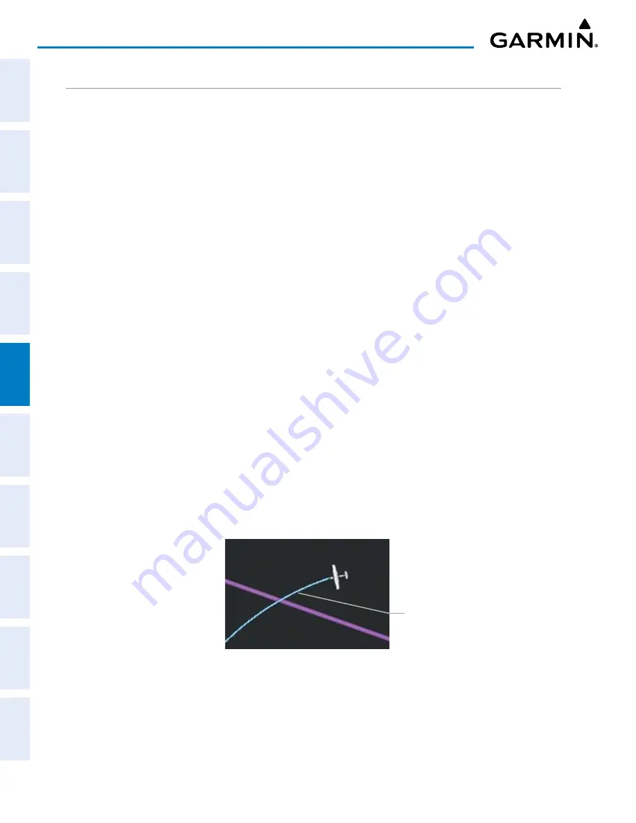
The Navigation Map can display a track vector that is useful in minimizing track angle error. The track
vector is a solid cyan line segment extended to a predicted location. The track vector look-ahead time is
selectable (30 sec, 60 sec (default), 2 min, 5 min, 10 min, 20 min) and determines the length of the track
vector. The track vector shows up to 90 degrees of a turn for the 30 and 60 second time settings. It is always
a straight line for the 2 min, 5 min, 10 min and 20 min settings.
Figure 5-17 Navigation Map -Track Vector
Track Vector


