


Switched Central Resource (SCR)
16KB
I-Cache
16KB
D-Cache
4KB ETB
ARM926EJ-S CPU
With MMU
ARM Subsystem
JTAG Interface
System Control
Input
Clock(s)
64KB ROM
8KB RAM
(Vector Table)
Power/Sleep
Controller
Pin
Multiplexing
PLL/Clock
Generator
w/OSC
General-
Purpose
Timer (x4)
Serial Interfaces
Audio Ports
McASP
w/FIFO
DMA
Peripherals
Display
Shared
Memory
LCD
Ctlr
128KB
RAM
External Memory Interfaces
Connectivity
EDMA3
(x2)
Control Timers
eHRPWM
(x2)
eCAP
(x3)
EMIFA(8b/16B)
NAND/Flash
16b SDRAM
DDR2/mDDR
Memory
Controller
RTC/
32-kHz
OSC
I C
(x2)
2
SPI
(x2)
UART
(x3)
McBSP
(x2)
Video
VPIF
Parallel
Port
uPP
EMAC
10/100
(MII/RMII)
MDIO
USB1.1
OHCI Ctlr
PHY
USB2.0
OTG Ctlr
PHY
HPI
MMC/SD
(8b)
(x2)
SATA
Customizable
Interface
PRU
Subsystem
Memory Protection
Introduction
82
SPRUH82C – April 2013 – Revised September 2016
Copyright © 2013–2016, Texas Instruments Incorporated
Overview
1.1
Introduction
The AM1808/AM1810 ARM microprocessor contains an ARM RISC CPU for general-purpose processing
and systems control. The AM1808/AM1810 ARM microprocessor consists of the following primary
components:
•
ARM subsystem and associated memories
•
A set of I/O peripherals
•
A powerful DMA subsystem and SDRAM EMIF interface
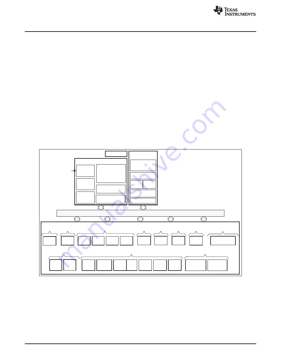
Block Diagram
A block diagram for the AM1808/AM1810 ARM microprocessor is shown in
.
1.2
ARM Subsystem
The ARM926EJ-S™ 32-bit RISC CPU in the ARM subsystem (ARMSS) acts as the overall system
controller. The ARM CPU performs general system control tasks, such as system initialization,
configuration, power management, user interface, and user command implementation. The
ARM
Subsystem
chapter describes the ARMSS components and system control functions that the ARM core
performs.
Figure 1-1. AM1808/AM1810 ARM Microprocessor Block Diagram
Note: Not all peripherals are available at the same time due to multiplexing.
DMA Subsystem
The DMA subsystem includes two instances of the enhanced DMA controller (EDMA3). For more
information, see the
Enhanced Direct Memory Access (EDMA3) Controller
chapter.


