background image

GD310-UL series VFD


Function parameter 

-50- 

Function 

code 

Name 

Description 

Default 

value 

Modify 

P01.20 

Hibernation 

restore delay 

time 

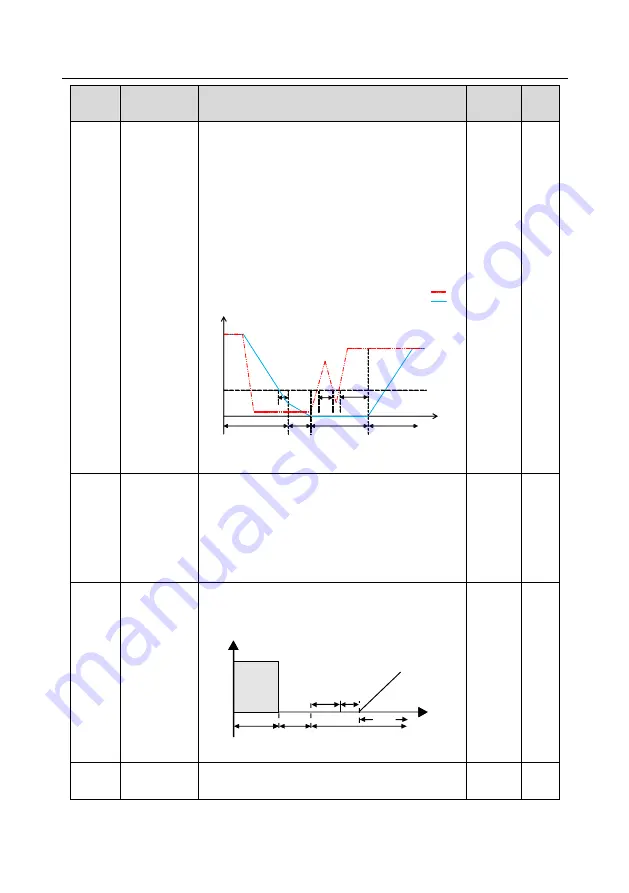
This function code determines the hibernation delay 

time.  When  the  running  frequency  of  the  VFD  is 

lower than the lower limit one, the VFD will pause to 

stand by.   

When the set frequency is above the lower limit one 

again and it lasts for the time set by P01.20, the VFD 

will run automatically. 

Note:

  The  time  is  the  total  value  when  the  set 

frequency is above the lower limit one. 

Sleep

Run


Set frequency curve:


Running frequency curve:  


t1 < P01.20, the VFD does not run


t0=P01.34, sleep delay

Run  


t2  

t1  


t0  

Frequency lower 

limit f0


Frequency f

Time t


Coast to 

stop

t1+t2 

P01.20, the VFD runs


Setting range: 0.0

–3600.0s (valid when P01.19=2) 

0.0s 

○ 

P01.21 

Restart after 

power off 

This  function  can  enable  the  VFD  start  or  not  after 

the power off and then power on. 

0: Disable   

1: Enable, if the starting need is met, the VFD will run 

automatically  after  waiting  for  the  time  defined  by 

P01.22.   

○ 

P01.22 

The waiting 

time of restart 

after power off 

The function determines  the  waiting  time  before  the 

automatic running of the VFD when powering off and 

then powering on.   

Output frequency


Running


Power off


Power on


Running


t

t1

t2

t1=P01.22

=

t2=P01.23

=


Setting range: 0.0

–3600.0s (valid when P01.21=1) 

1.0s 

○ 

P01.23 

Start delay 

time 

The  function  determines  the  brake  release  after  the 

running  command  is  given,  and  the  VFD  is  in  a 

0.0s 

○ 

Содержание GD310-011P-4-UL

Страница 1: ......

Страница 2: ...improved reliability Goodrive310 UL series VFDs apply modularized design to meet the specific demand of customers as well as the demand of the whole industry flexibly and follow the trend of industrial application to the VFDs on the premise of meeting general need of the market Powerful speed control torque control simple PLC flexible input output terminals pulse frequency given traverse control c...

Страница 3: ...nment 5 2 5 Installation confirmation 6 2 6 Basic commissioning 6 3 Product Overview 7 3 1 What this chapter contains 7 3 2 Basic principles 7 3 3 Product specification 8 3 4 Name plate 10 3 5 Type designation key 11 3 6 Rated specifications 11 3 6 1 The VFDs of AC 3PH 200V 240V 11 3 6 2 The VFDs of AC 3PH 380V 480V 12 3 6 3 The VFDs of AC 3PH 520V 600V 14 3 7 Structure diagram 14 4 Installation g...

Страница 4: ...ns 32 5 2 Keypad 32 5 3 Keypad displaying 34 5 3 1 Displayed state of stopping parameter 34 5 3 2 Displayed state of running parameters 35 5 3 3 Displayed state of fault 35 5 3 4 Displayed state of function codes editing 35 5 4 Keypad operation 35 5 4 1 How to modify the function codes of the VFD 36 5 4 2 How to set the password of the VFD 36 5 4 3 How to watch the VFD state through function codes...

Страница 5: ...Analog input 142 7 10 Analog output 143 7 11 Digital input 147 7 12 Digital output 153 7 13 Simple PLC 156 7 14 Multi step speed running 158 7 15 PID control 160 7 15 1 General steps of PID parameters setting 162 7 15 2 PID inching 162 7 16 Traverse running 165 7 17 Pulse counter 166 7 18 Fixed length control 167 7 19 Fault procedure 168 8 Fault tracking 172 8 1 What this chapter contains 172 8 2 ...

Страница 6: ...mand code 03H 195 10 4 2 Command code 06H 196 10 4 3 Command code 08H for diagnosis 197 10 4 4 Command code 10H continuous writing 198 10 4 5 The definition of data address 199 10 4 6 Fieldbus ratio values 203 10 4 7 Fault message response 204 10 4 8 Example of writing and reading 205 10 5 Common communication fault 209 Appendix A Expansion card 210 A 1 What this chapter contains 210 A 2 PROFIBUS ...

Страница 7: ... drawings 231 C 1 What this chapter contains 231 C 2 Keypad structure 231 C 2 1 Structure chart 231 C 2 2 Installation bracket optional 231 C 3 VFD structure 232 C 4 Dimensions for VFDs 232 C 4 1 Wall installation 232 C 4 2 Flange installation 234 C 4 3 Floor installation 236 C 5 Dimensions for VFDs of AC 3PH 520V 10 600V 10 238 C 5 1 Wall installation 238 C 5 2 Flange installation 238 Appendix D ...

Страница 8: ... D 8 Braking system 254 D 8 1 Select the braking components 254 D 8 2 Selecting the brake resistor cables 258 D 8 3 Placing the brake resistor 258 Appendix E Further information 260 E 1 Product and service inquiries 260 E 2 Feedback on INVT VFD manuals 260 E 3 Documents on the Internet 260 ...

Страница 9: ... electricians People working on the device should take part in professional electrical and safety training receive the certification and be familiar with all steps and requirements of installing commissioning operating and maintaining the device to avoid any emergency 1 3 Warning symbols Warnings caution you about conditions which can result in serious injury or death and or damage to the equipmen...

Страница 10: ...electrostatic Take measurements to avoid electrostatic discharge during related operation 1 4 1 Delivery and installation Please install the VFD on fire retardant material and keep the VFD away from combustible materials Connect the braking optional parts braking resistors braking units or feedback units according to the wiring diagram Do not operate on the VFD if there is any damage or components...

Страница 11: ...age is present inside the VFD during running Do not carry out any operation except for the keypad setting The VFD may start up by itself when P01 21 1 Do not get close to the VFD and motor The VFD cannot be used as Emergency stop device The VFD cannot be used to break the motor suddenly A mechanical braking device should be provided Besides the above items check to ensure the following ones before...

Страница 12: ...ws cables and other conductive matters to fall into the VFD during maintenance and component replacement Note Please select proper torque to tighten screws Keep the VFD parts and components away from combustible materials during maintenance and component replacement Do not carry out any isolation and pressure test on the VFD and do not measure the control circuit of the VFD by megameter Carry out ...

Страница 13: ...nd control keypad inside the packing box are complete If not please contact local dealers or INVT offices 2 3 Application confirmation Check the machine before beginning to use the VFD 1 Check the load type to verify that there is no overload of the VFD during work and check that whether the drive needs to modify the power degree 2 Check that the actual current of the motor is less than the rated ...

Страница 14: ... from flammable materials 4 Check that all control cables and power cables are run separately and the routing complies with EMC requirement 5 Check that all grounding systems are properly grounded according to the requirements of the VFD 6 Check that the free space during installation is sufficient according to the instructions in user s manual 7 Check that the installation conforms to the instruc...

Страница 15: ...shows the simplified main circuit diagram of the VFD The rectifier converts three phase AC voltage to DC voltage The capacitor bank of the intermediate circuit stabilizes the DC voltage The converter transforms the DC voltage back to AC voltage for the AC motor The brake pipe connects the external braking resistor to the intermediate DC circuit to consume the feedback energy when the voltage in th...

Страница 16: ...per tag between P1 and before connecting DC reactors and external braking units are optional 3 3 Product specification Function Specification Power input Input voltage V AC 3PH 200V 240V Rated voltage 220V AC 3PH 380V 480V Rated voltage 460V AC 3PH 520V 600V Rated voltage 575V Allowable Voltage Fluctuation 15 10 Input current A Refer to Rated specifications Input frequency Hz 50Hz or 60Hz Allowed ...

Страница 17: ...he combination and single setting channel Auto adjustment of the voltage Keep constant voltage automatically when the grid voltage transients Fault protection Provide more than 30 fault protection functions overcurrent overvoltage undervoltage overheating phase loss and overload etc Restart after rotating speed tracking Smooth starting of the rotating motor Peripheral interface Terminal analog inp...

Страница 18: ... phase to phase suitable for overvoltage categoryⅢ and shall provide protection for a rated impulse withstand voltage peak of 4kV For input voltage 323 480V transient surge suppression shall be installed on the line side of this equipment and shall be rated 480V phase to ground 480V phase to phase suitable for overvoltage category Ⅲ and shall provide protection for a rated impulse withstand voltag...

Страница 19: ...e Voltage degree 2 AC 3PH 200V 240V Rated voltage 220V 4 AC 3PH 380V 480V Rated voltage 460V 6 AC 3PH 520V 600V Rated voltage 575V Certification mark Used in America Certified by UL and CUL 3 6 Rated specifications 3 6 1 The VFDs of AC 3PH 200V 240V Model Rated output power kW Rated input current A Rated output current A GD310 0R7G 2 UL 0 75 5 4 5 GD310 1R5G 2 UL 1 5 7 7 7 GD310 2R2G 2 UL 2 2 11 1...

Страница 20: ... 2R2G 4 UL 2 2 5 8 5 0 GD310 004G 4 UL 4 13 5 9 5 GD310 5R5G 4 UL 5 5 19 5 14 GD310 7R5G 4 UL 7 5 25 18 5 GD310 011G 4 UL 11 32 25 GD310 015G 4 UL 15 40 32 GD310 018G 4 UL 18 5 47 38 GD310 022G 4 UL 22 56 45 GD310 030G 4 UL 30 70 60 GD310 037G 4 UL 37 80 75 GD310 045G 4 UL 45 94 92 GD310 055G 4 UL 55 128 115 GD310 075G 4 UL 75 160 150 GD310 090G 4 UL 90 190 180 GD310 110G 4 UL 110 225 215 GD310 13...

Страница 21: ... 200P 4 UL 200 385 380 GD310 220P 4 UL 220 430 425 GD310 250P 4 UL 250 485 480 GD310 280P 4 UL 280 545 530 GD310 315P 4 UL 315 610 600 GD310 350P 4 UL 350 625 650 GD310 400P 4 UL 400 715 720 GD310 500P 4 UL 500 890 860 Note The input current of VFDs G type 1 5 200kW P type 5 5 220kW is detected when the input voltage is 460V and there is no DC reactors and input output reactors The input current o...

Страница 22: ...0 090G 6 UL 90 118 120 GD310 110G 6 UL 110 145 150 Note The input current of VFDs 18 5 110kW is detected when the input voltage is 575V and there is no DC reactors and input output reactors The rated output current is defined when the output voltage is 575V The output current cannot exceed the rated output current and the output power cannot exceed the rated output power in the voltage range 3 7 S...

Страница 23: ... Overview for detailed information 7 Side cover Optional The side cover will increase the protective degree of the VFD The internal temperature of the VFD will increase too so it is necessary to derate the VFD at the same time 8 Control terminals See Installation guidelines for detailed information 9 Main circuit terminals See Installation guidelines for detailed information 10 Main circuit cable ...

Страница 24: ...stion some damage beyond the assured maintenance range may occur 4 2 Mechanical installation 4 2 1 Installation environment The installation environment is the safeguard for a full performance and long term stable functions of the VFD Check the installation environment as follows Environment Conditions Installation site Indoor Environment temperature 10 50 C If the ambient temperature of the VFD i...

Страница 25: ...m when the installation site altitude exceeds 3000m consult the local INVT dealer or office Vibration 5 88m s2 0 6g Installation direction The VFD should be installed on an upright position to ensure sufficient cooling effect Note Goodrive310 UL series VFDs should be installed in a clean and ventilated environment according to enclosure classification Cooling air must be clean free from corrosive ...

Страница 26: ...he VFDs of 460V G type 220 500kW P type 250 500kW Figure 4 2 Installation manner 1 Mark the hole location The location of the holes is shown in the dimension drawings in the Appendix C 2 Fix the screws or bolts to the marked locations 3 Put the VFD against the wall 4 Tighten the screws in the wall securely Note The flange installation of the VFDs of 220V 0 75 15kW and 460V G type 1 5 30kW P type 5...

Страница 27: ...llation Note The minimum space of B and C is 100mm 4 2 5 Multiple installations Parallel installation B C C B A A D Cold air Warm air Figure 4 4 Parallel installation Note Before installing the different sizes VFDs please align their top position for the convenience of later maintenance The minimum space of B D and C is 100mm ...

Страница 28: ...lines 20 4 2 6 Vertical installation Warm air Warm air Cool air Cool air Wind board Wind board Figure 4 5 Vertical installation Note Windscreen should be installed in vertical installation for avoiding mutual impact and insufficient cooling ...

Страница 29: ...Slanting installation W a r m a i r W a r m a i r W a r m a i r C o o l a i r C o o l a i r C o o l a i r Figure 4 6 Slanting installation Note Ensure the separation of the wind input and output channels in slanting installation for avoiding mutual impact ...

Страница 30: ... for the VFDs of 220V 18 5 55kW 460V G type 37kW P type 45kW Note The fuse DC reactor braking unit braking resistor input reactor input filter output reactor output filter are optional parts Please refer to Peripheral options and parts for detailed information P1 and are short circuited in factory for the VFDs of 220V 18 5kW 460V G type 37kW P type 45kW if need to connect with the DC rector please...

Страница 31: ...e short circuited in factory if need to connect with the DC rector please remove the jumper between P1 and 4 3 2 Terminals figure of main circuit Figure 4 10 Terminals of main circuit for the VFDs of 220V 0 75kW and 460V G type 1 5 2 2kW Figure 4 11 Terminals of main circuit for the VFDs of 220V 1 5 2 2kW and 460V G type 4 5 5kW P type 5 5 7 5kW Figure 4 12 Terminals of main circuit for the VFDs o...

Страница 32: ...VFDs of 220V 7 5kW and 460V G type 15 18 5kW P type 18 5 22kW Figure 4 14 Terminals of main circuit for the VFDs of 220V 11 15kW and 460V G type 22 30kW P type 30 37kW Figure 4 15 Terminals of main circuit for the VFDs of 220V 18 5 30kW and 460V G type 37 55kW P type 45 55kW and 575V 18 5 37kW ...

Страница 33: ...rcuit for the VFDs of 220V 37 55kW 460V G type 75 110kW P type 75 110kW and 575V 45 110kW POWER Figure 4 17 Terminals of main circuit for the VFDs of 460V G type 132 200kW P type 132 220kW Figure 4 18 Terminals of main circuit for the VFDs of 460V G type 220 315kW P type 250 350kW ...

Страница 34: ...tput 3 phase AC output terminals which are generally connected with the motor P1 DC reactor terminal 1 P1 and are connected with the terminals of DC reactor and are connected with the terminals of braking unit PB and are connected with the terminals of braking resistor Braking resistor 1 DC reactor terminal 2 braking unit terminal 1 Braking unit terminal 2 PB Braking resistor 2 PE Protective groun...

Страница 35: ...shared DC bus running mode current balance on the VFD input side must be considered during wiring and equalizing reactors are recommended to be configured If the terminal description is the machine does not provide the terminal as the external terminal 4 3 3 Wiring of terminals in main circuit 1 Connect the ground line of input power cable to the ground terminal of VFD PE directly and connect 3PH ...

Страница 36: ...lection and electrode open input selection Open collector output Shield layer Twisted pair Y1 10V external Open collector input S1 S2 S3 S4 S5 S6 S7 S8 HDI COM PW J1 J2 AO1 GND 0 10V 0 20mA 0 10V 0 20mA AO2 GND HDO CME CME RS485 communication 485 485 GND PE RO1A RO1B RO1C RO2A RO2B RO2C RO1 RO2 Profibus DB9 plug 24V PE J3 J4 AI1 AI2 AI3 GND V V I I PE 10V J5 Figure 4 21 Wiring of control circuit 4...

Страница 37: ...pply from external to internal Voltage range 12 24V 24V The VFD provides the power supply for users with a max output current of 200mA COM 24V common terminal S1 Switch input 1 1 Internal impedance 3 3kΩ 2 12 30V voltage input is available 3 The terminal is the dual direction input terminal supporting both NPN and PNP 4 Max input frequency 1kHz 5 All are programmable digital input terminal User ca...

Страница 38: ... jumper between COM and CME Torsional moment 35 ibf in Figure 4 23 U shaped jumper If the signal is from NPN transistor please set the U shaped jumper between 24V and PW as below according to the used power supply S1 S2 COM PW 24V COM 24V S1 S2 COM PW 24V COM 24V 24V Figure 4 24 NPN modes If the signal is from PNP transistor please set the U shaped jumper as below according to the used power suppl...

Страница 39: ...r These devices may require a separate fuse to cut off the short circuit current 4 4 3 Protecting the motor against thermal overload According to regulations the motor must be protected against thermal overload and the current must be switched off when overload is detected The VFD includes a motor thermal protection function that protects the motor and closes the output to switch off the current w...

Страница 40: ...JOG RUN STOP RST Figure 5 1 Keypad Note 1 The LED keypad is standard but the LCD keypad which can support various languages parameters copy and 10 line displaying is optional 2 It is necessary to use M3 screw or installation bracket to fix the external keypad The installation bracket for VFDs of 220V 0 75 15kW and 460V G type 1 5 30kW P type 5 5 37kW is optional but it is standard for the VFDs of ...

Страница 41: ...communication control state TRIP LED for faults LED on when the VFD is in the fault state LED off in normal state LED blinking means the VFD is in the pre alarm state 2 Unit LED Mean the unit displayed currently Hz Frequency unit RPM Rotating speed unit A Current unit Percentage V Voltage unit 3 Code displaying zone 5 figure LED display displays various monitoring data and alarm code such as set f...

Страница 42: ... 3 Keypad displaying The keypad displaying state of Goodrive310 UL series VFDs is divided into stopping state parameter running state parameter function code parameter editing state and fault alarm state and so on 5 3 1 Displayed state of stopping parameter When the VFD is in the stopping state the keypad will display stopping parameters which is shown in figure 5 2 In the stopping state various k...

Страница 43: ... Displayed state of fault If the VFD detects the fault signal it will enter into the fault pre alarm displaying state The keypad will display the fault code by flicking The TRIP LED on the keypad is on and the fault reset can be operated by the STOP RST on the keypad control terminals or communication commands 5 3 4 Displayed state of function codes editing In the state of stopping running or faul...

Страница 44: ...ter operation records and so on 2 This function code is not modifiable in running state but modifiable in stop state Example Set function code P00 01 from 0 to 1 The unit is blinking All digits are blinking The unit is blinking The unit is blinking The unit is blinking Note When setting and can be used to shift and adjust SHIFT PRG ESC PRG ESC PRG ESC PRG ESC DATA ENT DATA ENT DATA ENT Figure 5 3 ...

Страница 45: ... DATA ENT DATA ENT DATA ENT SHIFT Figure 5 4 Sketch map of password setting 5 4 3 How to watch the VFD state through function codes Goodrive310 UL series VFDs provide group P17 as the state inspection group Users can enter into P17 directly to watch the state All digits are blinking The unit is blinking The unit is blinking The unit is blinking The unit is blinking PRG ESC PRG ESC PRG ESC DATA ENT...

Страница 46: ...ues of the function parameter The fifth column Modify the modifying character of function codes the parameters can be modified or not and the modifying conditions below is the instruction means the set value of the parameter can be modified on stop and running state means the set value of the parameter cannot be modified on the running state means the value of the parameter is the real detection v...

Страница 47: ...gh speed control accuracy for accurate speed and torque control Relative to mode 1 this mode is more suitable for medium and small power 1 SVC mode 1 applying to AM No need to install encoders It is suitable in cases with high speed control accuracy for accurate speed and torque control at all power ratings 2 SVM control No need to install encoders It can improve the control accuracy with the adva...

Страница 48: ...ncy This parameter is used to set the maximum output frequency of the VFD Users should pay attention to this parameter because it is the foundation of the frequency setting and the speed of acceleration and deceleration Setting range P00 04 400 00Hz 60 00Hz P00 04 Upper limit of the running frequency The upper limit of the running frequency is the upper limit of the output frequency of the VFD whi...

Страница 49: ...on code P00 03 4 High speed pulse HDI setting The frequency is set by high speed pulse terminals The VFDs provide 1 high speed pulse input as the standard configuration The pulse frequency range is 0 00 50 00kHz 100 0 of the high speed pulse input setting corresponds to the maximum frequency in forward direction P00 03 and 100 0 corresponds to the maximum frequency in reverse direction P00 03 Note...

Страница 50: ...iven value feedback source of PID 8 MODBUS communication setting The frequency is set by MODBUS communication See P14 for detailed information 9 PROFIBUS CANopen communication setting The frequency is set by PROFIBUS CANopen communication See P15 for the detailed information 10 Ethernet communication setting reserved 11 Reserved Note A frequency and B frequency cannot set as the same frequency giv...

Страница 51: ...rom the max Output frequency to 0Hz P00 03 Goodrive310 UL series VFDs define four groups of ACC DEC time which can be selected by P05 The factory default ACC DEC time of the VFD is the first group Setting range of P00 11 and P00 12 0 0 3600 0s Depend on model P00 12 DEC time 1 Depend on model P00 13 Running direction 0 Runs at the default direction the VFD runs in the forward direction FWD REV ind...

Страница 52: ...W 2kHz G type 75 500kW 2kHz P type 90 500kW 2kHz 575V G type 22 55kW 4kHz G type 75 110kW 2kHz The advantage of high carrier frequency ideal current waveform little current harmonic wave and motor noise The disadvantage of high carrier frequency increasing the switch loss increasing VFD temperature and the impact to the output capacity The VFD needs to derate on high carrier frequency At the same ...

Страница 53: ...ent motor is motor 1 autotune P02 06 P02 07 P02 08 and when the current motor is motor 2 autotune P12 06 P12 07 P12 08 0 P00 16 AVR function selection 0 Invalid 1 Valid during the whole procedure The auto adjusting function of the VFD can cancel the impact on the output voltage of the VFD because of the bus voltage fluctuation 1 P00 17 VFD type 0 G type for the constant torque load of rated parame...

Страница 54: ...irect start up means the original frequency during the VFD starting See P01 02 for detailed information Setting range 0 00 50 00Hz 0 50Hz P01 02 Retention time of the starting frequency Set a proper starting frequency to increase the torque of the VFD during starting During the retention time of the starting frequency the output frequency of the VFD is the starting frequency And then the VFD will ...

Страница 55: ...elerates to decrease the output frequency during the set time When the frequency decreases to P01 15 the VFD stops 1 Coast to stop after the stop command becomes valid the VFD ceases the output immediately And the load coasts to stop at the mechanical inertia 0 P01 09 Starting frequency of DC braking The starting frequency of stop braking the VFD will carry on stop DC braking when the frequency is...

Страница 56: ...12 0 00 50 00s P01 13 Dead time of FWD REV rotation During the procedure of switching for rev rotation set the threshold by P01 14 which is as the table below Output frequency FWD REV T Starting frequency Shift after the zero frequency Shift after the starting frequency Setting range 0 0 3600 0s 0 0s P01 14 Shifting between FWD REV rotation Set the threshold point of the VFD 0 Switch after zero fr...

Страница 57: ... command is detected to be valid during powering on the VFD won t run and the system keeps in the protection state until the running command is canceled and enabled again 1 The terminal running command is valid when powering on If the running command is detected to be valid during powering on the system will start the VFD automatically after the initialization Note this function should be selected...

Страница 58: ...Run t2 t1 t0 Frequency lower limit f0 Frequency f Time t Coast to stop t1 t2 P01 20 the VFD runs Setting range 0 0 3600 0s valid when P01 19 2 0 0s P01 21 Restart after power off This function can enable the VFD start or not after the power off and then power on 0 Disable 1 Enable if the starting need is met the VFD will run automatically after waiting for the time defined by P01 22 0 P01 22 The w...

Страница 59: ...tion Default value Modify P02 00 Motor type 1 0 Asynchronous motor 1 Synchronous motor Note Switch the current motor by the switching channel of P08 31 0 P02 01 Rated power of AM 1 0 1 3000 0kW Depend on model P02 02 Rated frequency of AM 1 0 01Hz P00 03 the max frequency 60 00Hz P02 03 Rated speed of AM 1 1 36000rpm Depend on model P02 04 Rated voltage of AM 1 0 1200V P02 05 Rated current of AM 1...

Страница 60: ...f AM 1 0 0 100 0 57 0 P02 14 Magnetic saturation coefficient 4 for the iron core of AM1 0 0 100 0 40 0 P02 15 Rated power of SM 1 0 1 3000 0kW Depend on model P02 16 Rated frequency of SM 1 0 01Hz P00 03 the max frequency 60 00Hz P02 17 Number of poles pairs of SM 1 1 50 2 P02 18 Rated voltage of SM 1 0 1200V Depend on model P02 19 Rated current of SM 1 0 8 6000 0A P02 20 Stator resistor of SM 1 0...

Страница 61: ... the rated power and I is the rated current Setting range 0 10000 300 P02 24 Reserved P02 25 Reserved P02 26 Motor 1 overload protection 0 No protection 1 Common motor with low speed compensation Because the heat releasing effect of the common motors will be weakened the corresponding electric heat protection will be adjusted properly The low speed compensation characteristic mentioned here means ...

Страница 62: ...er display of motor 1 0 Display according to the motor type 1 Display all 0 P03 Group Vector control Function code Name Description Default value Modify P03 00 Speed loop proportional gain1 The parameters P03 00 P03 05 only apply to vector control mode Below the switching frequency 1 P03 02 the speed loop PI parameters are P03 00 and P03 01 Above the switching frequency 2 P03 05 the speed loop PI ...

Страница 63: ...range of P03 02 0 00Hz P03 05 Setting range of P03 03 0 200 0 Setting range of P03 04 0 000 10 000s Setting range of P03 05 P03 02 P00 03 max output frequency P03 06 Speed loop output filter 0 8 corresponds to 0 28 10ms 0 P03 07 Compensation coefficient of electromotion slip Slip compensation coefficient is used to adjust the slip frequency of the vector control and improve the speed control accur...

Страница 64: ...ng range 300 0 300 0 rated motor current 50 0 P03 13 Torque reference filter time 0 000 10 000s 0 010s P03 14 Upper frequency of forward rotation in vector control 0 Keypad P03 16 sets P03 14 P03 17 sets P03 15 1 AI1 2 AI2 3 AI3 4 Pulse frequency HDI setting upper limit frequency 5 Multi step setting upper limit frequency 6 MODBUS communication setting upper limit frequency 7 PROFIBUS CANopen comm...

Страница 65: ... setting methods 1 4 100 corresponds to three times of the motor current 0 P03 19 Upper braking torque source 0 P03 20 Keypad setting of electromotion torque The function code is used to set the limit of the torque Setting range 0 0 300 0 motor rated current 180 0 P03 21 Keypad setting of braking torque 180 0 P03 22 Flux weakening coefficient in constant power zone The usage of motor in weakening ...

Страница 66: ...03 24 P03 26 are invalid for vector mode 1000 P03 27 Vector control speed 0 Display the actual value 1 Display the setting value 0 P03 28 Compensation coefficient of static friction 0 0 100 0 Adjust P03 28 to compensate the coefficient of static friction Only valid when setting in 1Hz 0 0 P03 29 Compensation coefficient of dynamic friction 0 0 100 0 Adjust P03 29 to compensate the coefficient of s...

Страница 67: ... curve power of 2 0 P04 01 Torque boost of motor 1 Torque boost to the output voltage for the features of low frequency torque P04 01 is for the max Output voltage Vb P04 02 defines the percentage of closing frequency of manual torque to fb Torque boost should be selected according to the load The bigger the load is the bigger the boost is Too big torque boost is inappropriate because the motor wi...

Страница 68: ...e rated frequency of motor 1 Setting range of P04 08 0 0 110 0 the rated voltage of motor 1 0 00Hz P04 04 V F voltage 1 of motor 1 00 0 P04 05 V F frequency 2 of motor 1 00 00Hz P04 06 V F voltage 2 of motor 1 00 0 P04 07 V F frequency 3 of motor 1 00 00Hz P04 08 V F voltage 3 of motor 1 0 00 P04 09 V F slip compensation gain of motor 1 This function code is used to compensate the change of the ro...

Страница 69: ...0 P04 12 for the detailed function code instruction Note P04 group includes two sets of V F parameters of the motor which cannot display simultaneously Only the selected V F parameter can be shown The motor selection can be defined by terminals function the shift between motor 1 and motor 2 0 P04 14 Torque boost of motor 2 0 0 P04 15 Torque boost close of motor 2 20 0 P04 16 V F frequency 1 of mot...

Страница 70: ... channel at V F curve separation 0 Keypad the output voltage is determined by P04 28 1 AI1 2 AI2 3 AI3 4 HDI 5 Multi step speed 6 PID 7 MODBUS communication 8 PROFIBUS CANopen communication 9 Ethernet communication 10 Reserved Note 100 corresponds to the rated voltage of the motor 0 P04 28 Keypad setting voltage The function code is the voltage displaying when the voltage is set through keypad The...

Страница 71: ...output voltage of VFD in SVPWM mode during flux weakening Note Invalid in constant torque mode Output voltage Output frequency P04 33 1 00 Vb out b Setting range of P04 33 1 00 1 30 1 00 P05 Group Input terminals Function code Name Description Default value Modify P05 00 HDI input selection 0 High pulse input See P05 49 P05 54 1 Digital input See P05 09 0 P05 01 S1 terminals function selection 0 N...

Страница 72: ... Traverse pause stop at the current frequency 27 Traverse reset return to the center frequency 28 Counter reset 29 Torque control disabling 30 ACC DEC disabling 31 Counter trigging 32 Length reset 33 Cancel the frequency change setting temporarily 34 DC brake 35 Shift the motor 1 into motor 2 36 Shift the command to the keypad 37 Shift the command to the terminals 38 Shift the command to the commu...

Страница 73: ...abled BIT0 S1 virtual terminal BIT1 S2 virtual terminal BIT2 S3 virtual terminal BIT3 S4 virtual terminal BIT4 S5 virtual terminal BIT5 S6 virtual terminal BIT6 S7 virtual terminal BIT7 S8 virtual terminal BIT8 HDI virtual terminal 0x000 P05 13 Terminals control running mode Set the operation mode of the terminals control 0 2 wire control 1 comply the enable with the direction This mode is widely ...

Страница 74: ...and the direction is controlled by REV Sin is natural closed COM K SB2 SB1 FWD REV SIn The direction control is as below during operation Sln REV Previous direction Current direction ON OFF ON Forward Reverse Reverse Forward ON ON OFF Reverse Forward Forward Reverse ON OFF ON Decelerate to stop OFF 3 3 wire control 2 Sin is the enabling terminal on this mode and the running command is caused by SB...

Страница 75: ... again For example the valid STOP RST stop when PLC signal cycles stop fixed length stop and terminal control see P07 04 P05 14 Switch on delay of S1 terminal The function code defines the corresponding delay time of electrical level of the programmable terminals from switching on to switching off Si electrical level Si valid invalid invalid Switcn on delay Switcn off delay valid Setting range 0 0...

Страница 76: ...nal 0 000s P05 27 Switch off delay of S7 terminal 0 000s P05 28 Switch on delay of S8 terminal 0 000s P05 29 Switch off delay of S8 terminal 0 000s P05 30 Switch on delay of HDI terminal 0 000s P05 31 Switch off delay of HDI terminal 0 000s P05 32 Lower limit of AI1 The function code defines the relationship between the analog input voltage and its corresponding set value If the analog input volta...

Страница 77: ...tting range of P05 33 100 0 100 0 Setting range of P05 34 P05 32 10 00V Setting range of P05 35 100 0 100 0 Setting range of P05 36 0 000s 10 000s Setting range of P05 37 0 00V P05 39 Setting range of P05 38 100 0 100 0 Setting range of P05 39 P05 37 10 00V Setting range of P05 40 100 0 100 0 Setting range of P05 41 0 000s 10 000s Setting range of P05 42 10 00V P05 44 Setting range of P05 43 100 0...

Страница 78: ...t terminals 2 Length counting input length counter input terminals 0 P05 50 Lower limit frequency of HDI 0 000kHz P05 52 0 000kH z P05 51 Corresponding setting of HDI low frequency setting 100 0 100 0 0 0 P05 52 Upper limit frequency of HDI P05 50 50 000kHz 50 000k Hz P05 53 Corresponding setting of upper limit frequency of HDI 100 0 100 0 100 0 P05 54 HDI frequency input filter time 0 000s 10 000...

Страница 79: ...re alarm 16 Completion of simple PLC stage 17 Completion of simple PLC cycle 18 Setting count value arrival 19 Defined count value arrival 20 External fault valid 21 Length arrival 22 Running time arrival 23 MODBUS communication virtual terminals output 24 PROFIBUS CANopen communication virtual terminals output 25 Ethernet communication virtual terminals output 26 Voltage establishment finished 27...

Страница 80: ...delay time 0 000s P06 11 RO1 switch off delay time 0 000s P06 12 RO2 switch on delay time 0 000s P06 13 RO2 switch off delay time 0 000s P06 14 AO1 output 0 Running frequency 1 Set frequency 2 Ramp reference frequency 3 Running rotation speed relative to twice the motor synchronous speed 4 Output current relative to twice the rated current of the VFD 5 Output current relative to twice the rated cu...

Страница 81: ...o the low limit or upper limit output When the analog output is current output 1mA equals to 0 5V In different cases the corresponding analog output of 100 of the output value is different For detailed information please refer to analog output instructions in Chapter 7 10V 20mA 0 0 100 0 AO Setting range of P06 18 0 00V 10 00V Setting range of P06 19 P06 17 100 0 Setting range of P06 20 0 00V 10 0...

Страница 82: ...er s password 0 65535 The password protection will be valid when setting any non zero number 00000 Clear the previous user s password and make the password protection invalid After the set user s password becomes valid if the password is incorrect users cannot enter the parameter menu Only correct password can make the user check or modify the parameters Please remember all users passwords Retreat...

Страница 83: ... shifting key Press QUICK JOG to shift the displayed function code from right to left 3 Shift between forward rotations and reverse rotations Press QUICK JOG to shift the direction of the frequency commands This function is only valid in the keypad commands channels 4 Clear UP DOWN settings Press QUICK JOG to clear the set value of UP DOWN 5 Coast to stop Press QUICK JOG to coast to stop 6 Shift t...

Страница 84: ...FF BIT0 running frequency Hz on BIT1 set frequency Hz flickering BIT2 bus voltage Hz on BIT3 output voltage V on BIT4 output current A on BIT5 running rotation speed rpm on BIT6 output power on BIT7 output torque on BIT8 PID reference flickering BIT9 PID feedback value on BIT10 input terminals state BIT11 output terminals state BIT12 torque set value on BIT13 pulse counter value BIT14 length value...

Страница 85: ...he current stage in multi step speed BIT12 pulse counters BIT13 length value BIT14 upper limit frequency Hz on BIT15 reserved 0x00FF P07 08 Frequency coefficient 0 01 10 00 Displayed frequency running frequency P07 08 1 00 P07 09 Rotation speed coefficient 0 1 999 9 Mechanical rotation speed 120 displayed running frequency P07 09 motor pole pairs 100 0 P07 10 Linear speed coefficient 0 1 999 9 Lin...

Страница 86: ...actory bar code 3 0x0000 0xFFFF P07 24 Factory bar code 4 0x0000 0xFFFF P07 25 Factory bar code 5 0x0000 0xFFFF P07 26 Factory bar code 6 0x0000 0xFFFF P07 27 Type of present fault 0 No fault 1 IGBT U phase protection OUt1 2 IGBT V phase protection OUt2 3 IGBT W phase protection OUt3 4 Overcurrent during acceleration OC1 5 Overcurrent during deceleration OC2 6 Overcurrent during constant speed run...

Страница 87: ...d short circuit fault 1 ETH1 33 To ground short circuit fault 2 ETH2 34 Speed deviation fault dEu 35 Mal adjustment STo 36 Underload fault LL P07 33 Running frequency at present fault 0 00Hz P07 34 Ramp reference frequency at present fault 0 00Hz P07 35 Output voltage at the present fault 0V P07 36 Output current at present fault 0 0A P07 37 Bus voltage at present fault 0 0V P07 38 The max tempera...

Страница 88: ...e 0 0 3600 0s Depend on model P08 01 DEC time 2 Depend on model P08 02 ACC time 3 Depend on model P08 03 DEC time 3 Depend on model P08 04 ACC time 4 Depend on model P08 05 DEC time 4 Depend on model P08 06 Jogging frequency This parameter is used to define the reference frequency during jogging Setting range 0 00Hz P00 03 the max frequency 5 00Hz P08 07 Jogging ACC time The jogging ACC time means...

Страница 89: ...is illustrated as below of which the traverse is set by P08 15 and when P08 15 is set as 0 the traverse is 0 with no function Output frequency Jumping frequency Accelerate Decelerate per dec time Wobble frequency amplitude Fall time of wobble frequency Rise time of wobble frequency Center frequency Lower limit of wobble frequency Traverse range The traverse running is limited by upper and low freq...

Страница 90: ...35m Setting range of P08 20 0 65535m Setting range of P08 21 1 10000 Setting range of P08 22 0 01 100 00cm Setting range of P08 23 0 001 10 000 Setting range of P08 24 0 001 1 000 0m P08 20 Actual length 0m P08 21 Pulse per rotation 1 P08 22 Axle perimeter 10 00cm P08 23 Length ratio 1 000 P08 24 Length correcting coefficient 1 000 P08 25 Setting counting value The counter works by the input pulse...

Страница 91: ...wait maintenance Interval time of automatic fault reset the interval between the time when the fault occurs and the time when the reset action occurs Setting range of P08 28 0 10 Setting range of P08 29 0 1 3600 0s 0 P08 29 Interval time of automatic fault reset 1 0s P08 30 Frequency decreasing ratio of the dropping control The output frequency of the VFD changes as the load And it is mainly used ...

Страница 92: ... invalid Below is the wave form diagram Y RO1 RO2 Output frequency FDT level Lag T T Setting range of P08 32 0 00Hz P00 03 the max frequency Setting range of P08 33 0 0 100 0 FDT1 electrical level Setting range of P08 34 0 00Hz P00 03 the max frequency Setting range of P08 35 0 0 100 0 FDT2 electrical level 60 00Hz P08 33 FDT1 retention detection value 5 0 P08 34 FDT2 electrical level detection va...

Страница 93: ...e setting range 200 0 2000 0V In order to prevent customers set the value is too large it is recommended setting range Voltage 220V 460V 575V Range 360 390V 715 780V 950 1050V 220V voltage 380 0V 460V voltage 740 0V 575V voltage 1000 0V P08 39 Cooling fan running mode 0 Normal mode 1 The fan keeps running after power on 0 P08 40 PWM selection 0x00 0x21 LED ones PWM mode selection 0 PWM mode 1 thre...

Страница 94: ...alid when P00 06 0 or P00 07 0 1 Valid for all frequency setting manner 2 Invalid for multi step speed when multi step speed has the priority LED hundreds action selection during stopping 0 Setting is valid 1 Valid during running cleared after stopping 2 Valid during running cleared after receiving the stop command LED thousands keys and digital potentiometer integral function 0 The integral funct...

Страница 95: ...wer off LED tens Action selection when MODBUS set frequency off 0 Save when power off 1 Clear when power off LED hundreds The action selection when other frequency set frequency off 0 Save when power off 1 Clear when power off 0x000 P08 48 High bit of initial power consumption This parameter is used to set the original value of the power consumption The original value of the power consumption P08 ...

Страница 96: ...eases during magnetic flux braking while the cooling of the stator is more effective than the rotor P08 51 Current regulation coefficient on input side This function code is used to adjust the displayed current of the AC input side Setting range 0 00 1 00 0 56 P09 Group PID control Function code Name Description Default value Modify P09 00 PID reference source When the frequency command selection ...

Страница 97: ...MODBUS communication feedback 5 PROFIBUS CANopen communication feedback 6 Ethernet communication feedback 7 Reserved Note The reference and feedback channel cannot coincide otherwise PID cannot control effectively 0 P09 03 PID output feature 0 PID output is positive when the feedback signal exceeds the PID given value the output frequency of the VFD will decrease to balance the PID For example the...

Страница 98: ...eter determines the strength of the change ratio when PID adjustor carries out integral adjustment on the deviation of PID feedback and reference If the PID feedback changes 100 during the time the adjustment of integral adjustor ignoring the proportional effect and differential effect is the max Frequency P00 03 or the max Voltage P04 31 Longer the integral time stronger is the adjusting Setting ...

Страница 99: ...k detection value is smaller than or equals to the detected value and the lasting time exceeds the set value in P09 12 the VFD will report PID feedback offline fault and the keypad will display PIDE T Output frequency t1 t2 P09 11 t1 t2 so the inverter continues to work t2 P09 12 In running Fault output PIDE PIDE Setting range of P09 11 0 0 100 0 Setting range of P09 12 0 0 3600 0s 0 0 P09 12 Dete...

Страница 100: ... Limit to the maximum frequency 1 Limit to frequency A LED thousands 0 A B frequency the buffer of A frequency is invalid 1 A B frequency the buffer of A frequency is valid ACC DEC is determined by ACC time 4 of P08 04 P09 14 Proportional gain at low frequency Kp 0 00 100 00 1 00 P09 15 PID command of ACC DEC time 0 0 1000 0s 0 0s P09 16 PID output filter time 0 000 10 000s 0 000s P10 Group Simple...

Страница 101: ... selected multi step speeds are in the range of fmax fmax and it can be set continuously Goodrive310 UL series VFDs can set 16 stages speed selected by the combination of multi step terminals 1 4 select the setting by S terminals the corresponding function codes are P05 01 P05 09 corresponding to the speed 1 to speed 15 Output frequency Terminal 1 Terminal 2 Terminal 3 Terminal 4 ON ON ON ON ON ON...

Страница 102: ...N ON OFF OFF ON ON Terminal 3 OFF OFF OFF OFF ON ON ON ON Terminal 4 ON ON ON ON ON ON ON ON Step 8 9 10 11 12 13 14 15 0 0 P10 21 Running time of step 9 0 0s P10 22 Multi step speed 10 0 0 P10 23 Running time of step 10 0 0s P10 24 Multi step speed 11 0 0 P10 25 Running time of step 11 0 0s P10 26 Multi step speed 12 0 0 P10 27 Running time of step 12 0 0s P10 28 Multi step speed 13 0 0 P10 29 Ru...

Страница 103: ...et by P08 04 and P08 05 Setting range 0x0000 0xFFFF P10 36 PLC restart 0 Restart from the first step stop during running caused by the stop command fault or power loss run from the first stage after restart 1 Continue to run from the stop frequency stop during running caused by stop command and fault the VFD will record the running time automatically enter into the stage after restart and keep the...

Страница 104: ... VFD begin to decrease the running frequency at P11 02 to make the VFD generate power again The returning power can maintain the bus voltage to ensure a rated running of the VFD until the recovery of power Voltage degree 220V 460V 575V Frequency decre asing threshold 260V 530V 700V Note 1 Adjust the parameter properly to avoid the stopping caused by VFD protection during the switching of the grid ...

Страница 105: ...ned in P11 06 If it exceeds the level the VFD will run at stable frequency in ACC running or the VFD will derate to run during the constant running If it exceeds the level continuously the output frequency will keep on decreasing to the lower limit If the output current is detected to be lower than the limit level the VFD will accelerate to run Output frequency Output current Limiting point Consta...

Страница 106: ...to work after underload pre alarm and the VFD stops to run after overload fault 2 The VFD continues to work after overload pre alarm and the VFD stops to run after underload fault LED hundreds 0 Detection all the time 1 Detection in constant running Setting range of P11 09 P11 11 200 relative value is determined by the ones place of P11 08 Setting range of P11 10 0 1 3600 0s 150 P11 10 Overload pr...

Страница 107: ...time This parameter is used to see the speed deviation detection time Speed Actual detection value The set detection value t1 t2 t1 t2 so the inverter continues to work t2 P11 15 dEu In running Fault output Setting range of P11 15 0 0 10 0s 0 5s P11 16 Automatic frequency dec reasing at voltage drop 0 Invalid 1 Valid ensure rated output torque when voltage drop 0 P12 Group Motor 2 Function code Na...

Страница 108: ... rated power of the motor P12 01 initialize the motor parameter of P12 02 P12 05 60 00Hz P12 03 Rated speed of asynchronous motor 2 1 36000rpm Depend on model P12 04 Rated voltage of asynchronous motor 2 0 1200V Depend on model P12 05 Rated current of asynchronous motor 2 0 8 6000 0A Depend on model P12 06 Stator resistor of asynchronous motor 2 0 001 65 535Ω After finish the motor parameter autot...

Страница 109: ...or the iron core of AM2 0 0 100 0 40 0 P12 15 Rated power of synchronous motor 2 0 1 3000 0kW Set the parameter of the controlled asynchronous motor In order to ensure the controlling performance set the P12 151 P12 19 according to the name plate of the asynchronous motor Goodrive310 UL series VFDs provide the function of parameter autotuning Correct parameter autotuning comes from the correct set...

Страница 110: ...P12 22 will renew automatically These parameters are basic parameters controlled by vectors which directly impact the features When P00 15 1 the set value of P12 23 can be updated through autotuning automatically and there is no need to change the value of P12 23 when P00 15 2 the set value of P12 23 cannot be updated through autotuning please account and update the value of P12 23 Note Users cann...

Страница 111: ... Setting range 0 10000 P12 24 Initial pole position of synchronous motor 2 reserved 0 FFFFH reserved 0x0000 P12 25 Identification current of synchronous motor 2 reserved 0 50 the rated current of the motor reserved 10 P12 26 Motor 2 overload protection 0 No protection 1 Common motor with low speed compensation 2 Variable frequency motor without low speed compensation 2 P12 27 Motor 2 overload prot...

Страница 112: ...he motor type only the parameters relative to the current motor type are displayed for the convenient for the customers in this mode 1 All parameters are displayed all parameters are displayed in this mode 0 P13 Group Synchronous motor control Function code Name Description Default value Modify P13 00 Reduction coefficient of source current 0 0 100 0 80 0 P13 01 Original pole test mode 0 No test 1...

Страница 113: ...Reserved 0 65535 0 P13 11 Maladjustment detection time Adjust the response of anti maladjustment Bigger load inertia may increase the value but the response will be slower Setting range 0 0 10 0s 0 5s P13 12 High frequency compensation coefficient When the motor speed is faster than the rated speed the parameter is valid if vibration occurs to the motor please adjust the parameter Setting range 0 ...

Страница 114: ... The communication of the drive is unique in the communication net This is the fundamental for the point to point communication between the upper monitor and the drive Note The address of the slave cannot set to 0 1 P14 01 Communica tion baud ratio Set the digital transmission speed between the upper monitor and the VFD 0 1200BPS 1 2400BPS 2 4800BPS 3 9600BPS 4 19200BPS 5 38400BPS 6 57600BPS 7 115...

Страница 115: ...s invalid When the function code is set as non zero if the interval time between two communications exceeds the communication overtime the system will report 485 communication faults CE Generally set it as invalid set the parameter in the continuous communication to monitor the communication state 0 0s P14 05 Transmission fault processing 0 Alarm and stop freely 1 No alarm and continue to run 2 No...

Страница 116: ...orresponds to 100 0 the rated current of the motor 5 Upper frequency of forward rotation 0 Fmax unit 0 01Hz 6 Upper frequency of reverse rotation 0 Fmax unit 0 01Hz 7 Electromotion torque upper limit 0 3000 1000 corresponds to 100 0 of the rated current of the motor 8 Braking torque upper limit 0 2000 1000 corresponds to 100 0 of the rated current of the motor 9 Virtual input terminals command Ran...

Страница 117: ...E frequency value 100 kHz 16 Terminals input state 17 Terminals output state 18 PID given 100 19 PID feedback 100 20 Motor rated torque 21 Control word 0 P15 14 PZD3 sending 0 P15 15 PZD4 sending 0 P15 16 PZD5 sending 0 P15 17 PZD6 sending 0 P15 18 PZD7 sending 0 P15 19 PZD8 sending 0 P15 20 PZD9 sending 0 P15 21 PZD10 sending 0 P15 22 PZD11 sending 0 P15 23 PZD12 sending 0 P15 24 Temporarily vari...

Страница 118: ...ction Function code Name Description Default value Modify P16 00 Speed setting of Ethernet communication 0 Self adapting 1 100M full duplex 2 100M semiduplex 3 10M full duplex 4 10M semiduplex The function code is used to set the Ethernet communication speed 0 P16 01 IP address 1 0 255 Set the IP address of Ethernet communication The format of IP address P16 09 P16 10 P16 11 P16 12 For example IP ...

Страница 119: ...urrent Display current output current of the VFD Range 0 0 3000 0A 0 0A P17 05 Motor speed Display the rotation speed of the motor Range 0 65535RPM 0 RPM P17 06 Torque current Display current torque current of the VFD Range 3000 0 3000 0A 0 0A P17 07 Exciting current Display current exciting current of the VFD Range 3000 0 3000 0A 0 0A P17 08 Motor power Display current power of the motor Setting ...

Страница 120: ... Counting value Display the current counting number of the VFD Range 0 65535 0 P17 19 AI1 input voltage Display analog AI1 input signal Range 0 00 10 00V 0 00V P17 20 AI2 input voltage Display analog AI2 input signal Range 0 00 10 00V 0 00V P17 21 AI3 input voltage Display analog AI2 input signal Range 10 00 10 00V 0 00V P17 22 HDI input frequency Display HDI input frequency Range 0 000 50 000kHz ...

Страница 121: ...ated motor current 0 0 P17 32 Magnetic flux linkage Display the magnetic flux linkage of the motor Range 0 0 200 0 0 0 P17 33 Exciting current reference Display the exciting current reference in the vector control mode Range 3000 0 3000 0A 0 0A P17 34 Torque current reference Display the torque current reference in the vector control mode Range 3000 0 3000 0A 0 0A P17 35 AC current Display the val...

Страница 122: ...o the installation list in chapter two Original powering operation Check to ensure there is no mistake in wiring and power supply switch on the air switch of the AC power supply on the input side of the VFD to power on the VFD 8 8 8 8 8 will be displayed on the keypad and the contactor closes normally When the character on the nixie tubs changes to the set frequency the VFD has finished the initia...

Страница 123: ...d repower on Set autotuning Set P00 15 1 Set P00 15 3 Press RUN to autotune and then stop Set running frequency Set P00 00 P00 00 0 P00 00 1 SVPWM control mode P00 00 2 Set P03 Set P03 Set P04 Set P01 Run Stop End Set P00 01 P00 02 Set P00 15 2 Synchronous motor Asynchronous motor Note If fault occurs please do as the Fault Tracking Estimate the fault reason and settle the issue Besides P00 01 and...

Страница 124: ...lative parameters table Function code Name Description Default value P00 00 Speed control mode 0 SVC mode 0 apply to AM and SM 1 SVC mode 1 applying to AM 2 SVM control 1 P00 01 Run command channel 0 Keypad running command 1 Terminal running command channel LOCAL REMOT flickering 2 Communication running command channel LOCAL REMOT on 0 P00 02 Communication running commands 0 MODBUS communication c...

Страница 125: ...umber of poles pairs for synchronous motor 1 1 50 2 P02 18 Rated voltage of synchronous motor 1 0 1200V Depend on model P02 19 Rated current of synchronous motor 1 0 8 6000 0A Depend on model P05 01 P0 5 09 Multi function digital input terminals S1 S8 HDI function selection 36 Shift the command to keypad 37 Shift the command to terminals 38 Shift the command to communication P07 01 Parameter copy ...

Страница 126: ...ic field of the motor and torque current the current heft generating torque by controlling and measuring the stator current vector according to the principles of beamed magnetic field to control the range and phase of these two hefts This method can realize the decoupling of exciting current and torque current to adjust the high performance of asynchronous motors Goodrive310 UL series VFDs are emb...

Страница 127: ... and SM 1 SVC mode 1 applying to AM 2 SVM control 1 P00 15 Motor parameter autotuning 0 No operation 1 Rotating autotuning 2 Static autotuning 1 autotune totally 3 Static autotuning 2 autotune part of the parameters 0 P02 00 Motor type 1 0 Asynchronous motor 1 Synchronous motor 0 P03 00 Speed loop proportional gain1 0 200 0 20 0 P03 01 Speed loop integral time1 0 000 10 000s 0 200s P03 02 Low swit...

Страница 128: ...e 3 Analog AI2 setting torque 4 Analog AI3 setting torque 5 Pulse frequency HDI setting torque 6 Multi step torque setting 7 MODBUS communication setting torque 8 PROFIBUS CANopen communication setting torque 9 Ethernet communication setting torque 10 Reserved Note Setting modes 2 6 100 corresponds to three times of the rated current of the motor 0 P03 12 Keypad setting torque 300 0 300 0 rated mo...

Страница 129: ...ion torque source 0 Keypad setting upper limit frequency P03 20 sets P03 18 P03 21 sets P03 19 1 AI1 2 AI2 3 AI3 4 HDI 5 MODBUS communication 6 PROFIBUS CANopen communication 7 Ethernet communication 8 Reserved Note setting mode 1 4 100 corresponds to three times of the motor current 0 P03 19 Upper braking torque source 0 P03 20 Keypad setting of electromotion torque 0 0 300 0 rated current of the...

Страница 130: ...sponding 1 3th 1 7th or 2th power of V F curve because the actual torque is 2 squared or 3 squared of the rotating speed Output voltage Output frequency Linear type Square type Torque down V F curve power of 1 3 Torque down V F curve power of 1 7 Torque down V F curve power of 2 0 Vb fb Goodrive310 UL series VFDs provide multi dots V F curve the user can change the output V F curve by setting the ...

Страница 131: ...ps compensation gain SVPWM control belongs to the open loop mode If the load of the motor transients suddenly the fluctuation of the rotation speed may occur In the cases where the high accuracy speed is needed slip compensation gain internal output adjustment can be set to compensate the speed change caused by load fluctuation Setting range of slip compensation gain 0 200 of which 100 corresponds...

Страница 132: ...ernet CAN P00 06 A frequency command selection Keypad setting frequency P00 10 0 1 2 3 4 5 When the user selects the user defined V F curve function in Goodrive310 UL series VFDs they can set the given channel of voltage and frequency and the corresponding ACC DEC time or the two can combine to form a real time curve Note the application of V F curve separation can be used in many cases with vario...

Страница 133: ...r 1 P04 03 P04 07 00 00Hz P04 06 V F voltage 2 of motor 1 0 0 110 0 0 0 P04 07 V F frequency 3 of motor 1 P04 05 P02 02 or P04 05 P02 16 00 00Hz P04 08 V F voltage 3 of motor 1 0 0 110 0 0 0 P04 09 V F slip compensation gain of motor 1 0 0 200 0 100 0 P04 10 Vibration control factor at low frequency of motor 1 0 100 10 P04 11 Vibration control factor at high frequency of motor 1 0 100 10 P04 12 Vi...

Страница 134: ... 5 Multi step speed 6 PID 7 MODBUS communication 8 PROFIBUS CANopen communication 9 Ethernet communication 10 Reserved 0 P04 28 Keypad setting voltage 0 0 100 0 rated motor voltage 100 0 P04 29 Voltage increasing time 0 0 3600 0s 5 0s P04 30 Voltage decreasing time 0 0 3600 0s 5 0s P04 31 Maximum output voltage P04 32 100 0 rated motor voltage 100 0 P04 32 Minimum output voltage 0 0 P04 31 rated m...

Страница 135: ...ue 0 1 2 3 4 5 6 7 8 P03 21 Braking torque upper limit keypad setting Keypad AI1 AI2 AI3 HDI MODBUS PROFIBUS Erthernet CAN 0 1 2 3 4 5 6 7 8 P03 20 Torque control P17 09 0 1 2 3 4 5 6 7 Keypad 8 9 P03 16 AI1 AI2 AI3 HDI MODBUS PROFIBUS Erthernet CAN Multi stage speed 0 1 2 3 4 5 6 7 Keypad 8 9 P03 17 Output torque Starting 0 1 2 P03 19 P03 18 P03 15 P03 14 The upper limit of the electromotion torq...

Страница 136: ...ue 10 Reserved Note Setting modes 2 6 100 corresponds to three times of the rated current of the motor 0 P03 12 Keypad setting torque 300 0 300 0 rated motor current 50 0 P03 13 Torque reference filter time 0 000 10 000s 0 010s P03 14 Upper frequency of forward rotation in vector control 0 Keypad P03 16 sets P03 14 P03 17 sets P03 15 1 AI1 2 AI2 3 AI3 4 Pulse frequency HDI setting upper limit freq...

Страница 137: ...ing of braking torque 0 0 300 0 rated motor current 180 0 P17 09 Output torque 250 0 250 0 0 0 P17 15 Torque reference 300 0 300 0 rated current of the motor 0 0 7 6 Parameters of the motor Physical accident may occur if the motor starts up suddenly during autotune Please check the safety of surrounding environment of the motor and the load before autotune The power is still applied even the motor...

Страница 138: ...running command channel P00 01 2 MODBUS communication channel PROFIBUS CANopen communication channel Start Select Run command channel P00 01 Motor shifting P08 31 Terminal 35 Motor 1 shift To Motor 2 communication setting 2009H Motor 1 Motor 2 Invalid Valid BIT0 1 00 BIT0 1 01 P08 31 LED ones set 0 Ethernet communication channel P08 31 LED ones set 1 P08 31 LED ones set 2 P08 31 LED ones set 3 The...

Страница 139: ...s motors can autotune the parameters of P02 06 P02 10 while the synchronous motors can autotune the parameters of P02 20 P02 23 3 During the motor autotune do not to de couple the motor from the load if static autotune is selected Because only some parameters of the motor are involved the control performance is not as better as the rotation autotune The asynchronous motors can autotune the paramet...

Страница 140: ...M 1 0 1200V Depend on model P02 05 Rated current of AM 1 0 8 6000 0A Depend on model P02 06 Stator resistor of AM 1 0 001 65 535Ω Depend on model P02 07 Rotor resistor of AM 1 0 001 65 535Ω Depend on model P02 08 Leakage inductance of AM 1 0 1 6553 5mH Depend on model P02 09 Mutual inductance of AM 1 0 1 6553 5mH Depend on model P02 10 Non load current of AM1 0 1 6553 5A Depend on model P02 15 Rat...

Страница 141: ...ated speed of AM 2 1 36000rpm Depend on model P12 04 Rated voltage of AM 2 0 1200V Depend on model P12 05 Rated current of AM 2 0 8 6000 0A Depend on model P12 06 Stator resistor of AM 2 0 001 65 535Ω Depend on model P12 07 Rotor resistor of AM 2 0 001 65 535Ω Depend on model P12 08 Leakage inductance of AM 2 0 1 6553 5mH Depend on model P12 09 Mutual inductance of AM 2 0 1 6553 5mH Depend on mode...

Страница 142: ...where the reverse rotation may occur it is better to select starting after DC braking and then starting after rotation speed tracking Note it is recommended to use the direct starting to drive synchronous motor 1 The starting logic figure of starting after the running command during the normal powering on Jogging running N 1f 1t P00 11 ACC time P00 12 DEC time A C C D E C P00 03 AC C D EC P00 03 1...

Страница 143: ...er the power off Running Stoppin g FWD REV Whether the running command terminal is valid N Invalid Y P00 01 Running command channel Keypad Comm unicati on Terminal 3 The starting logic figure of starting after the automatic fault reset VFD fault In running The fault reset times of the VFD P08 28 The interval time of the fault reset time of the VFD P08 29 Fault reset and the VFD starts to run Displ...

Страница 144: ...to stop 1 Coast to stop 0 P01 09 Starting frequency of DC braking 0 00Hz P00 03 the max frequency 0 00Hz P01 10 Waiting time of DC braking 0 00 50 00s 0 00s P01 11 DC braking current 0 0 100 0 0 0 P01 12 DC braking time 0 00 50 00s 0 00s P01 13 Dead time of FWD REV rotation 0 0 3600 0s 0 0s P01 14 Shifting between FWD REV rotation Set the threshold point of the VFD 0 Switch after 0 frequency 1 Swi...

Страница 145: ...ause 21 ACC DEC time option 1 22 ACC DEC time option 2 30 ACC DEC prohibition P08 06 Jogging frequency 0 00Hz P00 03 the max frequency 5 00Hz P08 07 Jogging ACC time 0 0 3600 0s Depend on model P08 08 Jogging DEC time 0 0 3600 0s Depend on model P08 00 ACC time 2 0 0 3600 0s Depend on model P08 01 DEC time 2 0 0 3600 0s Depend on model P08 02 ACC time 3 0 0 3600 0s Depend on model P08 03 DEC time ...

Страница 146: ...ection 0 1 UP DOWN enabling Digital potentiometer enabling 0 P00 03 1 A frequency command the Max output frequency 0 UP DOWN enabling 0 valid invalid valid Invalid Terminal function 12 Frequency increasing decreasing setting temporal clear Terminal function 33 Frequency increasing decreasing setting temporal clear 0 0 1 2 3 4 5 6 7 8 9 10 11 Keypad AI1 PROFIBUS MODBUS PID Multi stage speed Simple ...

Страница 147: ... 44 and P08 45 can be set to increase or decrease the set frequency quickly Sx Sy Up terminal function selection 10 DOWN terminal function selection 11 UP terminal state DOWN terminal state T F T T UP terminal frequency increasing integral rate P08 44 DOWNterminal frequency increasing integral rate P08 45 Related parameters list Function code Name Description Default value P00 03 Max output freque...

Страница 148: ... frequency setting UP 11 Decreasing frequency setting DOWN 12 Cancel the frequency change setting 13 Shift between A setting and B setting 14 Shift between combination setting and A setting 15 Shift between combination setting and B setting P08 42 Keypad data control 0x000 0x1223 LED ones frequency enable selection 0 Both keys and digital potentiometer adjustments are valid 1 Only keys adjustment ...

Страница 149: ...ns frequency control selection 0 Only valid when P00 06 0 or P00 07 0 1 All frequency means are valid 2 When the multi step are priority it is invalid to the multi step LED hundreds action selection when stop 0 Setting valid 1 Valid in the running clear after stop 2 Valid in the running clear after receiving the stop commands 0x000 P08 45 UP terminals frequency changing ratio 0 01 50 00Hz s 0 50 H...

Страница 150: ...ection AI1 input voltage AI2 input voltage AI3 input voltage HDI input frequency AI3 AI1 AI2 HDI P05 00 0 HDI is high speed pulse input 1 HDI is switch input P05 49 0 frequency setting input 1 counter input 2 length counter input Analog curve input setting Analog input filter Related parameters list Function code Name Description Default value P05 00 HDI input selection 0 High pulse input 1 Digita...

Страница 151: ...put frequency setting source 1 Counter input high speed pulse counter input terminals 2 Length counting input length counter input terminals 0 P05 50 Lower limit frequency of HDI 0 000kHz P05 52 0 000kHz P05 51 Corresponding setting of HDI low frequency setting 100 0 100 0 0 0 P05 52 Upper limit frequency of HDI P05 50 50 000kHz 50 000kHz P05 53 Corresponding setting of upper limit frequency of HD...

Страница 152: ...inal current of the motor 20 Reserved 0 1 P06 00 0 open collector high speed pulse output 1 open collector output P06 01 P06 02 P06 03 P06 04 output selection Analog output curve setting Analog output selection Analog output filter setting Output instructions Set value Function Instructions 0 Running frequency 0 the max output frequency 1 Set frequency 0 the max output frequency 2 Ramp given frequ...

Страница 153: ...current of the motor 0 2 times of the rated current of the motor 23 Exciting current relative to the rated current of the motor 0 2 times of the rated current of the motor 24 30 Reserved Related parameters list Function code Name Description Default value P06 00 HDO output 0 Open collector pole high speed pulse output 1 Open collector pole output 0 P06 14 AO1 output 0 Running frequency 1 Set frequ...

Страница 154: ...g AO1 output of lower limit 0 00V 10 00V 0 00V P06 19 Upper output limit of AO1 P06 17 100 0 100 0 P06 20 The corresponding AO1 output of upper limit 0 00V 10 00V 10 00V P06 21 AO1 output filter time 0 000s 10 000s 0 000s P06 22 Lower output limit of AO2 100 0 P06 24 0 0 P06 23 Corresponding AO2 output of lower limit 0 00V 10 00V 0 00V P06 24 Upper output limit of AO2 P06 22 100 0 100 0 P06 25 The...

Страница 155: ...e selection 2 23 Simple PLC pause 25 PID control pause 28 Counter reset 29 Torque control disabling 26 Traverse pause stop at the current frequency 30 ACC DEC disabling 32 Length reset 33 Frequency increasing decreasing setting clear 34 DC braking 3 3 wire running control 7 Fault reset 11 Frequency setting decreasing DOWN 15 Shifting between the combination setting and B frequency 19 Multi stage s...

Страница 156: ...nt to the VFD the VFD will report the fault and stop 10 Frequency setting up UP This parameter is used to modify the increasing and decreasing command during the external terminal given frequency K1 K2 K3 UP terminal DOWN terminal UP DOWN clearing terminals COM Frequency increasing decreasing setting clear terminal can cancel the assistant channel frequency set by the internal UP DOWN of the VFD t...

Страница 157: ... P08 02 P08 03 ON ON ACC DEC time 4 P08 04 P08 05 22 ACC DEC time selection 2 23 Simple PLC stop reset Restart simple PLC and clear the memory state of PLC 24 Simple PLC pause Program pause during PLC implement Run at the current speed stage After cancel the function simple PLC continues to run 25 PID control pause Temporal PID invalid and the VFD will output at the current frequency 26 Traverse p...

Страница 158: ... running command channel and the running command channel will come back to the original state if function terminal is invalid 38 Switch commands to communication After the function terminal become valid the running command channel will be shifted into communication running command channel and the running command channel will come back to the original state if function terminal is invalid 39 Pre ex...

Страница 159: ...eed terminal 1 17 Multi step speed terminal 2 18 Multi step speed terminal 3 19 Multi step speed terminal 4 20 Multi step speed pause 21 ACC DEC time 1 22 ACC DEC time 2 23 Simple PLC stop reset 24 Simple PLC pause 25 PID control pause 26 Traverse Pause stop at present frequency 27 Traverse reset return to center frequency 28 Counter reset 29 Torque control disabling 30 ACC DEC disabling 31 Counte...

Страница 160: ... terminal BIT6 S7 virtual terminal BIT7 S8 virtual terminal BIT8 HDI virtual terminal 0x000 P05 13 Terminals control running mode 0 2 wire control 1 1 2 wire control 2 2 3 wire control 1 3 3 wire control 2 0 P05 14 Switch on delay of S1 terminal 0 000 50 000s 0 000s P05 15 Switch off delay of S1 terminal 0 000 50 000s 0 000s P05 16 Switch on delay of S2 terminal 0 000 50 000s 0 000s P05 17 Switch ...

Страница 161: ...n collector pole input can be selected into high speed pulse input terminal or common switch input terminal by function code 0 1 2 3 4 5 29 30 P06 01 P06 03 P06 04 P06 02 T delay T delay T delay T delay 0 1 P06 05 default as 0 default as 0 default as 1 default as 5 P06 00 0 1 0 1 0 1 Delay 0 1 1 1 1 1 P17 13 P07 40 Fault Fault Run Y BIT0 HDO BIT1 ROI BIT2 RO2 BIT3 P06 05 P17 13 P07 40 P06 00 P06 0...

Страница 162: ...tput ON signal when the VFD is in the pre exciting state 14 Overload pre alarm Output ON signal if the VFD is beyond the pre alarm point Refer to P11 08 P11 10 for the detailed instruction 15 Underload pre alarm Output ON signal if the VFD is beyond the pre alarm point Refer to P11 11 P11 12 for the detailed instruction 16 Simple PLC stage completion Output signal if the simple PLC stage is comple...

Страница 163: ...llector pole high speed pulse output 1 Open collector pole output 0 P06 01 Y output 0 Invalid 1 In operation 2 Forward rotation operation 3 Reverse rotation operation 4 Jogging operation 5 The VFD fault 6 Frequency degree test FDT1 7 Frequency degree test FDT2 8 Frequency arrival 9 Zero speed running 10 Upper limit frequency arrival 11 Lower limit frequency arrival 12 Ready for operation 13 Pre ma...

Страница 164: ... state at present fault 0 P17 13 Digital output terminals state 0 7 13 Simple PLC Simple PLC function is also a multi step speed generator The VFD can change the running frequency direction to meet the need of processing according to the running time automatically In the past this function needs to be assisted by external PLC but now the VFD can realize this function by itself The series VFDs can ...

Страница 165: ...0 0 0 P10 07 The running time of step 2 0 0 6553 5s min 0 0s P10 08 Multi step speed 3 100 0 100 0 0 0 P10 09 The running time of step 3 0 0 6553 5s min 0 0s P10 10 Multi step speed 4 100 0 100 0 0 0 P10 11 The running time of step 4 0 0 6553 5s min 0 0s P10 12 Multi step speed 5 100 0 100 0 0 0 P10 13 The running time of step 5 0 0 6553 5s min 0 0s P10 14 Multi step speed 6 100 0 100 0 0 0 P10 15...

Страница 166: ...estart 0 Restart from the first stage 1 Continue to run from the stop frequency 0 P10 34 Simple PLC 0 7 step ACC DEC time 0x0000 0XFFFF 0000 P10 35 Simple PLC 8 15 step ACC DEC time 0x0000 0XFFFF 0000 P05 01 P05 09 Digital input function selection 23 Simple PLC stop reset 24 Simple PLC pause P06 01 P06 04 Digital output function selection 15 Underload pre alarm 16 Completion of simple PLC stage P1...

Страница 167: ...T11 BIT12 BIT13 BIT14 BIT15 P00 10 ACC time 1 P00 12 DEC time 1 P08 00 ACC time 2 P08 01 DEC time 2 P08 02 ACC time 3 P08 03 DEC time 3 P08 04 ACC time 4 P08 15 DEC time 4 00 01 10 11 The ACC DEC time selection of Stage 8 15 of PLC Multi stage speed output Running command Multi stage speed 0 Multi stage speed 1 Multi stage speed 15 ON OFF OFF ON Terminal function 16 Multi stage speed terminal 1 Te...

Страница 168: ...min 0 0s P10 30 Multi step speed 14 100 0 100 0 0 0 P10 31 Running time of step 14 0 0 6553 5s min 0 0s P10 32 Multi step speed 15 100 0 100 0 0 0 P10 33 Running time of step 15 0 0 6553 5s min 0 0s P10 34 Simple PLC 0 7 step ACC DEC time 0x0000 0XFFFF 0000 P10 35 Simple PLC 8 15 step ACC DEC time 0x0000 0XFFFF 0000 P05 01 P05 09 Digital input function selection 16 Multi step speed terminal 1 17 M...

Страница 169: ... difference between the feedback signal and reference If the static difference occurs in the direction of reference change such as reference increase where the feedback is always less than the reference after system stabilizes continue increasing the proportional gain otherwise decrease the proportional gain Repeat this process until the static difference becomes small Integral time Ti the output ...

Страница 170: ...sappear Record the Ti and set the integral time to 150 180 of the current value Then integral time commissioning is finished c Ensure the derivative time Td Generally it is not necessary to set Td which is 0 If it needs to be set set it to 30 of the value without vibration via the same method with P and Ti d Commissioning the system with and without load and then adjust the PID parameter until it ...

Страница 171: ...ime Response 调整前 调整后 响应 时间 t Control short vibration Short vibration period and the same set value with the derivative time Td mean that the derivative time is strong Shortening the derivative time Td can control the vibration When setting the derivative time as 0 00 namely no derivation control is useless to control the vibration decrease the gain 调整前 调整后 响应 时间 t 调整前 调整后 响应 时间 t 调整前 调整后 时间 t 响应 B...

Страница 172: ... 00 10 00s 0 00s P09 07 Sampling cycle T 0 000 10 000s 0 100s P09 08 PID control deviation limit 0 0 100 0 0 0 P09 09 Output upper limit of PID P09 10 100 0 max frequency or max voltage 100 0 P09 10 Output lower limit of PID 100 0 P09 09 max frequency or max voltage 0 0 P09 11 Detection value of feedback offline 0 0 100 0 0 0 P09 12 Detection time of feedback offline 0 0 3600 0s 1 0s P09 13 PID ad...

Страница 173: ...ncy the buffer of A frequency is invalid 1 A B frequency the buffer of A frequency is valid ACC DEC is determined by ACC time 4 of P08 04 P17 00 Setting frequency 0 00Hz P00 03 the max frequency 0 00Hz P17 23 PID reference 100 0 100 0 0 0 P17 24 PID feedback 100 0 100 0 0 0 7 16 Traverse running Traverse is applied in some industries such as textile chemical fiber and cases where traverse and conv...

Страница 174: ...DEC time 1 0 0 3600 0s P05 01 P05 09 Digital input function selection 26 Traverse Pause stop at present frequency 27 Traverse reset return to center frequency P08 15 Traverse range 0 0 100 0 relative to the set frequency 0 0 P08 16 Sudden jumping frequency range 0 0 50 0 relative to the traverse range 0 0 P08 17 Traverse boost time 0 1 3600 0s 5 0s P08 18 Traverse declining time 0 1 3600 0s 5 0s 7...

Страница 175: ...8 Counting value Given counting value arrival output Set counting value arrival output Function code Name Description Default value P05 00 HDI input selection 0 High pulse input 1 Digital input 0 P05 40 Corresponding setting of the upper limit of AI2 0 P05 01 P05 09 Digital input function selection 28 Counter reset 31 Counter trigger P06 01 P06 04 Digital output function selection 17 Completion of...

Страница 176: ...1 Digital input 0 P05 49 HDI high speed pulse input function selection 0 Frequency setting input 1 Counter input 2 Length counting input 0 P05 01 P05 09 Digital input function selection 32 Length reset P06 01 P06 04 Digital output function selection 20 Length arrival P08 19 Setting length 0 65535m 0 P08 20 Actual length 0 65535m 0 P08 21 Pulse per rotation 1 10000 1 P08 22 Axle perimeter 0 01 100 ...

Страница 177: ...t3 4 Overcurrent during acceleration OC1 5 Overcurrent during deceleration OC2 6 Overcurrent during constant speed running OC3 7 Overvoltage during acceleration OV1 8 Overvoltage during deceleration OV2 9 Overvoltage during constant speed running OV3 10 Bus undervoltage UV 11 Motor overload OL1 12 VFD overload OL2 13 Phase loss on input side SPI 14 Phase loss on output side SPO 15 Rectifier module...

Страница 178: ...unning frequency at present fault 0 00Hz P07 34 Ramp reference frequency at present fault 0 00Hz P07 35 Output voltage at the present fault 0V P07 36 Output current at present fault 0 0A P07 37 Bus voltage at present fault 0 0V P07 38 The max temperature at present fault 0 0 C P07 39 Input terminals state at present fault 0 P07 40 Output terminals state at present fault 0 P07 41 Running frequency ...

Страница 179: ...urrent at the last but one faults 0V P07 52 Output current at the last but one fault 0 0A P07 53 Bus voltage at the last but one fault 0 0V P07 54 The max temperature at the last but one fault 0 0 C P07 55 Input terminals state at the last but one fault 0 P07 56 Output terminals state at the last but one fault 0 ...

Страница 180: ...on codes P07 33 P07 40 P07 41 P7 48 P07 49 P07 56 show drive operation data at the time the latest 3 faults occurred 8 5 Fault instruction and solution Do as the following after the VFD fault 1 Check to ensure there is nothing wrong with the keypad If not please contact the local INVT office 2 If there is nothing wrong please check P07 and ensure the corresponding recorded fault parameters to conf...

Страница 181: ...rrent during deceleration OC3 6 Overcurrent during constant speed running OV1 7 Overvoltage during acceleration The input voltage is abnormal There is large energy feedback No braking components Braking energy is not open Check the input power Check if the DEC time of the load is too short or the VFD starts during the rotation of the motor or it needs to increase the energy consumption components ...

Страница 182: ...ture is too high The time of overload running is too long Refer to the overcurrent solution Redistribute dredge the wind channel or change the fan Low the ambient temperature Check and reconnect Change the power Change the power unit Change the main control panel OH2 16 Inverter module overheat EF 17 External fault SI external fault input terminals action Check the external device input CE 18 485 ...

Страница 183: ...edback source disappear Check the PID feedback signal Check the PID feedback source bCE 23 Braking unit fault Braking circuit fault or damage to the braking pipes The external braking resistor is not sufficient Check the braking unit and change new braking pipe Increase the braking resistor END 24 Running time reached The actual running time of the VFD is above the internal setting running time As...

Страница 184: ... keypad E DP 29 PROFIBUS communication fault Communication address is not correct Corresponding resistor is not dialed The files of main stop GSD does not set sound Check related setting E NET 30 Ethernet communication fault The Ethernet address is not set right The Ethernet communication is not selected to right The ambient interference is too strong Check the related setting Check the communicat...

Страница 185: ...r dEu 34 Speed deviation fault The load is too heavy or stalled Check the load and ensure it is normal Increase the detection time Check whether the control parameters are normal STo 35 Mal adjustment fault The control parameters of the synchronous motors not set properly The autotune parameter is not right The VFD is not connected to the motor Check the load and ensure it is normal Check whether ...

Страница 186: ...d setting is right or not Normal running Check the voltage of UVW VFD fault If the motor configuration is right or not Set a right motor configuration If the load is too heavy Reduce the load if the motor is locked caused by heavy load Motor fault Yes No No Yes Yes Normal Yes Yes Normal Abnormal normal Commun ication Terminal Keypad Yes Abnormal No No No No No No Normal Normal Abnormal Yes Normal ...

Страница 187: ...rameter Check the given frequency Check the load Yes No Yes No Yes No Yes No Yes No Yes No Yes No 8 6 3 Overvoltage OV fault Check if the voltage range is in the standard one or not Check if the ACC DEC time is too short Check if the load motor is in abnormal reverse running Ensure the power supply meets the need Check If UVW is short circuited to the earth and the configuration of the output side...

Страница 188: ...range Ensure the power supply meet the need Check if the air switch and contactor on the inside is off or abnormal or not Switch on the air switch and contactor and settle the abnormal Adjust the power supply Ensure the power off reason and settle the abnormal If the it is the VFD fault contact our company Check if there is big Power device in the same power supply Yes No Yes No Yes No Yes No ...

Страница 189: ...speed all the time Select right motor Low the load Change the motor Set proper carrier frequency Add output filter If the it is the VFD fault contact our company Yes No Yes No Yes No Yes No Yes No Yes No Yes No Yes NO Check if the parameter is right or not Check if it is frequency invertering motor Check if the load is too heavy Check if the 3 phase motor is balance Check if the carrier frequency ...

Страница 190: ...peed loss occurs to the VFD during ACC Check if the ACC time is too short If the it is the VFD fault or interference please contact with our company Overcurrent If the it is the VFD fault or interference please contact with our company Check if it performs parameter autotune Modify the torque boost Check if the torque boost is too high 过电流 Check if the motor is special Reduce the inertia of the lo...

Страница 191: ...k if there is interference source Parameters autotune Check if the ACC DEC time is too short Set right motor type and parameters Check if it needs parameters autotune Change the motor Check if the motor is short circuited to the earth Settle the short circuit problem and configure the motor cables rightly Overcurrent Check if the motor type and parameters are right Check if the parameter of curren...

Страница 192: ...ion There are no tools or dangerous objects Voltage Ensure the main circuit and control circuit are normal Measurement by millimeter Conforming to the manual Keypad Ensure the display is clear enough Visual examination The characters are displayed normally Ensure the characters are displayed totally Visual examination Conforming to the manual Main circuit For public use Ensure the screws are tight...

Страница 193: ...riginal value 0 85 Resistors Ensure whether there is replacement and splitting caused by overheating Smelling and visual examination NA Ensure that there is no offline Visual examination or remove one ending to coagulate or measure with multimeter The resistors are in 10 of the standard value Transformer and reactor Ensure there is no abnormal vibration noise and smelling Hearing smelling and visu...

Страница 194: ...ervice representative for more details on the maintenance Visit the official website 9 3 Cooling fan The VFD s cooling fan has a minimum life span of 25 000 operating hours The actual life span depends on the VFD usage and ambient temperature The operating hours can be found through P07 14 Fan failure can be predicted by the increasing noise from the fan bearings If the VFD is operated in a critic...

Страница 195: ...hours charging 50 rated voltage for 2 hours charging 75 rated voltage for 2 hours charging 100 rated voltage for 2 hours Use voltage adjusting power supply to charge the VFD The right selection of the voltage adjusting power supply depends on the supply power of the VFD Single phase 220V AC 2A power surge is applied to the VFD of single three phase 220V AC The VFD of single three phase 220V AC can...

Страница 196: ...hange electrolytic capacitors if the working hours of electrolytic capacitors in the VFD are above 35000 Please contact the local offices or dial our national service hotline 400 700 9997 for detailed operation 9 5 Power cable Read and follow the instructions in chapter Safety Precautions Ignoring the instructions may cause physical injury or death or damage to the equipment 1 Stop the drive and d...

Страница 197: ... no difference Modbus network is a controlling network with single master and multiple slaves which means that there is only one device performs as the master and the others are the slaves on one Modbus network The master means the device which has active talking right to send message to Modbus network for the controlling and inquiring to other devices The slave means the passive device which send...

Страница 198: ...d make the shield layer as the grounding wires during RS485 remote communication In the cases with less devices and shorter distance it is recommended to use 120Ω terminal resistor as the performance will be weakened if the distance increase even though the network can perform well without load resistor 10 3 2 1 Single application Figure 1 is the site Modbus connection figure of single VFD and PC ...

Страница 199: ...the RS485 industrial fieldbus standards The two ends are connected to terminal resistors of 120Ω which is shown as Figure 10 2 Figure 10 3 is the simply connection figure and Figure 10 4 is the real application figure 1 2 3 4 32 120 Ohm 120 Ohm Figure 10 2 Chrysanthemum connection 1 2 3 31 Master A B A B Figure 10 3 Chrysanthemum connection VFD Address 1 VFD VFD Address n Earth 485 485 Earth 485 4...

Страница 200: ...municate by RTU mode in Modbus network every 8bit byte in the message includes two 4Bit hex characters Compared with ACSII mode this mode can send more data at the same baud rate Code system 1 start bit 7 or 8 digital bit the minimum valid bit can be sent firstly Every 8 bit frame includes two hex characters 0 9 A F 1 even odd check bit If there is no checkout the even odd check bit is inexistent ...

Страница 201: ...ansmission time of 3 5 bytes ADDR Communication address 0 247 decimal system 0 is the broadcast address CMD 03H read slave parameters 06H write slave parameters DATA N 1 DATA 0 The data of 2 N bytes are the main content of the communication as well as the core of data exchanging CRC CHK low bit Detection value CRC 16BIT CRC CHK high bit END T1 T2 T3 T4 transmission time of 3 5 bytes 10 3 2 2 RTU c...

Страница 202: ... receiving data is different from the setting value there is an error in the communication CRC check The checkout uses RTU frame format The frame includes the frame error detection field which is based on the CRC calculation method The CRC field is two bytes including 16 figure binary values It is added into the frame after calculated by transmitting device The receiving device recalculates the CR...

Страница 203: ...d The following command format is illustrated by hex a number with H means hex and one hex occupies one byte The command code is used to read the working stage of the VFD For example read continuous 2 data content from0004H from the VFD with the address of 01H read the content of data address of 0004H and 0005H the frame structure is as below RTU master command message from the master to the VFD S...

Страница 204: ...ommand message is sent to the VFD with the address of 01H and ADDR occupies one byte CMD 03H means the message is received from the VFD to the master for the response of reading command and CMD occupies one byte Byte number means all byte number from the byte excluding the byte to CRC byte excluding the byte 04 means there are 4 byte of data from the byte number to CRC CHK low bit which are digita...

Страница 205: ...e of 3 5 bytes ADDR 02H CMD 06H High bit of writing data address 00H Low bit of writing data address 04H High bit of data content 13H Low bit of data content 88H Low bit of CRC C5H High bit of CRC 6EH END T1 T2 T3 T4 transmission time of 3 5 bytes Note Section 10 4 1 and 10 4 2 mainly describe the command format and the detailed application will be mentioned in 10 4 8 with examples 10 4 3 Command ...

Страница 206: ...High bit of CRC 14H END T1 T2 T3 T4 transmission time of 3 5 bytes 10 4 4 Command code 10H continuous writing Command code 10H means that if the master writes data to the VFD the data number depends on the data number in the command code The max continuous reading number is 16 For example write 5000 1388H to 0004H of the VFD whose slave address is 02H and 50 0032H to 0005H the frame structure is a...

Страница 207: ...h byte 00 ffH low byte 00 ffH The high byte is the group number before the radix point of the function code and the low byte is the number after the radix point But both the high byte and the low byte should be changed into hex For example P05 06 the group number before the radix point of the function code is 05 then the high bit of the parameter is 05 the number after the radix point 06 then the ...

Страница 208: ...meter list of other functions Function instruction Address definition Data meaning instruction R W attribute Communication control command 2000H 0001H forward running R W 0002H reverse running 0003H forward jogging 0004H reverse jogging 0005H stop 0006H coast to stop 0007H fault reset 0008H jogging stop Address of communication setting 2001H Communication setting frequency 0 Fmax unit 0 01Hz R W 2...

Страница 209: ...H Voltage setting value special for V F separation 0 1000 1000 corresponds to the 100 0 R W 200DH AO output setting 1 1000 1000 1000 corresponds to 100 0 R W 200EH AO output setting 2 1000 1000 1000 corresponds to 100 0 R W SW 1 of the VFD 2100H 0001H forward running R 0002H forward running 0003H stop 0004H fault 0005H POFF state 0006H pre exciting state SW 2 of the VFD 2101H Bit0 0 ready for oper...

Страница 210: ... 00 10 00V unit 0 01V R Analog input 3 300EH 0 00 10 00V unit 0 01V R Analog input 4 300FH R Read input of high speed pulse 1 3010H 0 00 50 00kHz unit 0 01Hz R Read input of high speed pulse 2 3011H R Read the current stage of multi step speed 3012H 0 15 R External length 3013H 0 65535 R External counting 3014H 0 65535 R Torque setting 3015H 300 0 300 0 unit 0 1 R Identifying code of the VFD 3016H...

Страница 211: ...er and the integer can be called fieldbus ratio values The fieldbus ratio values are referred to the radix point of the setting range or default value in the function parameter list If there are figures behind the radix point n 1 then the fieldbus ratio value m is 10n Take the table as the example Function code Name Description Setting range Default value Modification attribute P01 20 Wake up from...

Страница 212: ...t 02H Illegal data address Some of the operation addresses are invalid or not allowed to access Especially the combination of the register and the transmitting bytes are invalid 03H Illegal value When there are invalid data in the message framed received by slave Note This error code does not indicate the data value to write exceed the range but indicate the message frame is an illegal frame 04H O...

Страница 213: ...or the objection in a typical processing it will send the message again or modify the corresponding order For example set the running command channel of the VFD P00 01 parameter address is 0001H with the address of 01H to 03 the command is as following VFD address Write command Parameters address Parameters data CRC check But the setting range of running command channel is 0 2 if it is set to 3 be...

Страница 214: ... message is as below VDF address Read command Byte number Type of present fault Type of the last fault Type of the last but one fault CRC check Type of the last but two fault Type of the last but three fault Type of the last but four fault See from the returned data all fault types are 0023H decimal 35 with the meaning of maladjustment STo 10 4 8 2 Example of writing command 06H Make the VFD with ...

Страница 215: ... is 2710H The command sent by the master Parameters address VFD address Write command CRC check Parameters data If the operation is successful the response may be as below the same with the command sent by the master Parameters address VFD address Write command CRC check Parameters data Note the blank in the above command is for illustration The blank cannot be added in the actual application unle...

Страница 216: ...inuous writing command VFD address Parameters address CRC check Data number Example 2 set the ACC time of 01H VFD as 10s and the DEC time as 20s Function code Name Description Default value Modify P00 11 ACC time 1 ACC time means the time needed if the VFD speeds up from 0Hz to the max One P00 03 DEC time means the time needed if the VFD speeds down from the max Output frequency to 0Hz P00 03 Good...

Страница 217: ...ommands during actual applications 10 5 Common communication fault Common communication faults no response to the communication or the VFD returns abnormal fault The possible reason for no response to the communication Selecting wrong serial interface for example if the converter is COM1 selecting COM2 during the communication The baud rate digital bit end bit and check bit are not the same with t...

Страница 218: ...tandard two wire cable or fiber optic cable Baud rate is from 9 6Kbit s to 12Mbit s The maximum bus cable length is between 100 m and 1200 m specific length depending on the selected transmission rate see chapter Technical Data Up to 31 nodes can be connected to the same PROFIBUS network when repeaters aren t used But if use repeaters up to 127 nodes can be connected to the same PROFIBUS network s...

Страница 219: ...d to PROFIBUS network In PROFIBUS network VFD is a subsidiary device The following functions can be completed using EC TX 103 communication card Send control commands to VFD start stop fault reset etc Send speed or given torque signal to VFD Read state and actual values from VFD Modify VFD parameter Please refer to the description of function codes in Group P15 for the commands supported by the VF...

Страница 220: ...hree copper columns M3x10 User s manual Please contact the company or suppliers if there is something missing Notice will not be given for the reason of product upgrades A 2 6 Installation of EC TX 103 communication card A 2 6 1 Mechanical installation of EC TX 103 communication card 1 Installation ambient Ambient temperature 0 C 40 C Relative humidity 5 95 Other climate conditions no drew ice rai...

Страница 221: ...dress is the only address of PROFIBUS on the bus The address which is among 00 99 is shown with two figures and is selected by the spinning switch on the module The left switch shows the first number and the right one show the second number Node address 10 x the first digital value the second digital value x 1 2 Bus terminals There is a bus terminal in each heading and ending to avoid error during...

Страница 222: ...tive data twisted pair cables 1 4 RTS Sending requirement 5 GND_BUS Isolation ground 6 5V BUS Isolated 5V DC power supply 7 Unused 8 A Line Negative data twisted pair cables 2 9 Unused Housing SHLD PROFIBUS shielded cable 5V and GND_BUS are used in the fieldbus terminals Some devices such as light transceiver RS485 may get external power supply from these pins RTS is used in some devices to determ...

Страница 223: ...wire m B wire m 9 6 1200 1200 19 2 1200 1200 93 75 1200 1200 187 5 1000 600 500 400 200 1500 200 12000 100 Transmission line parameters Transmission rate kbps A wire m B wire m Impedance Ω 135 165 100 130 Capacitance per unit length pF m 30 60 Loop Resistance Ω km 110 Core wire diameter mm 0 64 0 53 Line core cross section mm2 0 34 0 22 Besides shielding twisted pair copper wires PROFIBUS can also...

Страница 224: ...sion rate more than 500K bit s The plug is available on the market which connects directly to data input and output cable Bus plug connection can be on or off at any time without interruption of data communications of other station A 2 7 System configuration 1 Master station and VFD should be configured so that the master station can communicate with the module after correctly installing EC TX 103...

Страница 225: ...4 GSD file In PROFIBUS network each PROFIBUS subsidiary station needs GSD file device description document which used to describe the characteristics of PROFIBUS DP devices GSD file contains all defined parameters including baud rate information length amount of input output data meaning of diagnostic data A CD ROM will be offered in which contains GSD file extension name is gsd for fieldbus adapt...

Страница 226: ...a PKW1 Parameter identification PKW2 array index number PKW3 parameter value 1 PKW4 parameter value 2 Process data CW Control word from master to slave SW state word from slave to master PZD process data decided by users From master to slave output given value from slave to master input actual value PZD area process data area PZD area of communication message is designed for control and monitor VF...

Страница 227: ...Mission message From master station to VFD Control word CW The first word of PZD is control word CW of VFD due to different control word CW of PWM rectifier regenerative part and VFD part Illustration is depart in next two tables Control word CW of Goodrive310 UL Bit Name Value State Description 0 7 Command byte 1 Forward running 2 Reverse running 3 Forward jogging 4 Reverse jogging 5 Decelerate t...

Страница 228: ...0 3000 1000 corresponds to 100 0 the rated current of the motor 5 Set value of the forward rotation upper limit frequency 0 Fmax unit 0 01Hz 6 Set value of the reversed rotation upper limit frequency 0 Fmax unit 0 01Hz 7 Electromotion torque upper limit 0 3000 1000 corresponds to 100 0 of the rated current of the motor 8 Braking torque upper limit 0 2000 1000 corresponds to 100 0 of the rated curr...

Страница 229: ...1 Motor 2 feedback 2 Motor 3 feedback 3 Motor 4 no feedback 11 Motor type feedback 1 Synchronous motor 0 Asynchronous motor 12 Overload alarm 1 Overload pre alarm 0 Non overload pre alarm 13 Run stop mode 0 Keypad control 1 Terminal control 14 2 Communication control 3 Reserved 15 Heartbeat feedback 1 Heartbeat feedback 0 No heartbeat feedback Actual value ACT From 2nd word to 12th of PZD task mes...

Страница 230: ...n marks PKW1 value area PKW area describes treatment of parameter identification interface PKW interface is a mechanism which determine parameters transmission between two communication partners such as reading and writing parameter values Process data Request mark response mark Parameter address Faultcode Parameters Structure of PKW area PKW Parameter identification area In the process of periodi...

Страница 231: ...ter value double word only change RAM 2 3 or 4 4 Modification parameter value one word RAM and EEPROM are modified 1 3 or 4 5 Modification parameter value double word RAM and EEPROM are modified 2 3 or 4 Request label 2 modification parameter value one word only change RAM 3 modification parameter value double word only change RAM 5 modification parameter value double word RAM and EPROM are modifi...

Страница 232: ... is in PKW4 Request From master to VFD PKW1 00 01 PKW2 00 10 PKW3 00 00 PKW4 00 00 CW xx xx PZD2 xx xx PZD3 xx xx PZD12 xx xx CW Request 0010 Parameter address 0001 Request for reading parameter values Response From VFD to master PKW1 00 01 PKW2 00 10 PKW3 00 00 PKW4 50 00 CW xx xx PZD2 xx xx PZD3 xx xx PZD12 xx xx CW Response 5000 Parameter value of address 10 0001 Response parameter values refre...

Страница 233: ...he parameter is instead of others Request From master to VFD PKW1 PKW2 PKW3 PKW4 CW PZD2 PZD3 PZD12 Response xx xx xx xx xx xx xx xx xx xx xx xx 00 0A xx xx Example 2 Write process data into VFD VFD parameter selects 2 PID Reference from PZD3 which can be achieved by setting P15 03 as 2 In each request frame parameters will use PZD3 to update until re select a parameter Request From master to conv...

Страница 234: ...or The length of user parameter data sets is different from that of network configuration process during module initialization process 2 Flicker frequency 2Hz user parameter data error The length or content of user parameter data sets is different from that of network configuration process during module initialization process 3 Flicker frequency 4Hz PROFIBUS communication ASIC initialization error...

Страница 235: ...exceeded motor torque and current are automatically restricted The function protects the input bridge of the drive against overload 2 The ratings apply at ambient temperature of 40 C 3 It is important to check that in Common DC systems the power flowing through the common DC connection does not exceed PN B 2 2 Derating The load capacity decreases if the installation site ambient temperature exceed...

Страница 236: ...60Hz 5 maximum rate of change 20 s B 4 Motor connection data Motor type Asynchronous induction motor or synchronous permanent magnet motor Voltage 0 to U1 3 phase symmetrical Umax at the field weakening point Short circuit protection The motor output is short circuit proof by IEC 61800 5 1 Frequency 0 400Hz Frequency resolution 0 01Hz Current Refer to Ratings Power limit 1 5 times the PN Field wea...

Страница 237: ...marking The CE mark is attached to the drive to verify that the drive follows the provisions of the European Low Voltage and EMC Directives B 5 2 UL and CUL marking The markings such as UL and CUL on the nameplate vary depending on actual certification status The AC 3PH 200V 240V and 380V 480V drive models have been certified to comply with UL 61800 5 1 and C22 2 No 274 17 and the AC 3PH 520V 600V...

Страница 238: ... provisions 1 The optional EMC filter is selected according to the options and installed as specified in the EMC filter manual 2 The motor and control cables are selected as specified in this manual 3 The drive is installed according to the instructions given in this manual 4 For the maximum motor cable length see B 4 1 EMC compatibility and motor cable length This product may cause radio inferenc...

Страница 239: ...ucture C 2 1 Structure chart 870 123 9 4 R5 82 0 115 0 C 2 2 Installation bracket optional Note It is necessary to use M3 screw or installation bracket to fix the external keypad The installation bracket for VFDs of 220V 0 75 15kW and 460V G type 1 5 30kW P type 5 5 37kW is optional but it is standard for the VFDs of 220V 18 5 55kW and 460V G type 37 500kW P type 45 500kW and 575V Installation bra...

Страница 240: ... UL series VFD Dimension drawings 232 C 3 VFD structure C 4 Dimensions for VFDs C 4 1 Wall installation Wall installation of 220V 0 75 15kW VFDs Wall installation of 460V G type 1 5 30kW P type 5 5 37kW VFDs ...

Страница 241: ...2 H1 H2 D1 Installation hole GD310 0R7G 2 UL 126 115 193 175 174 5 Ø5 GD310 1R5G 2R2G 2 UL 146 131 263 243 5 181 Ø6 GD310 004G 5R5G 2 UL 170 151 331 5 303 5 216 Ø6 GD310 7R5G 2 UL 230 210 342 311 216 Ø6 GD310 011G 015G 2 UL 255 237 407 384 245 Ø7 GD310 018G 030G 2 UL 270 130 555 540 325 Ø7 GD310 037G 055G 2 UL 325 200 680 661 365 Ø9 5 Wall installation dimension of 460V G type 1 5 200kW Model W1 W...

Страница 242: ...0 Ø11 Wall installation dimension of 460V P type 5 5 220kW Model W1 W2 H1 H2 D1 Installation hole GD310 5R5P 7R5P 4 UL 146 131 263 243 5 181 Ø6 GD310 011P 015P 4 UL 170 151 331 5 303 5 216 Ø6 GD310 018P 022P 4 UL 230 210 342 311 216 Ø6 GD310 030P 037P 4 UL 255 237 407 384 245 Ø7 GD310 045P 055P 4 UL 270 130 555 540 325 Ø7 GD310 075P 110P 4 UL 325 200 680 661 365 Ø9 5 GD310 132P 220P 4 UL 500 180 8...

Страница 243: ...el W1 W2 W3 W4 H1 H2 H3 H4 D1 D2 Installation hole GD310 0R7G 2 UL 150 115 130 7 5 234 220 190 16 5 174 5 65 5 Ø5 GD310 1R5G 2R2G 2 UL 170 131 150 9 5 292 276 260 10 181 79 5 Ø6 GD310 004G 5R5G 2 UL 191 151 174 11 5 370 351 324 15 216 2 113 Ø6 GD310 7R5G 2 UL 250 210 234 12 375 356 334 10 216 108 Ø6 GD310 011G 015G 2 UL 275 237 259 11 445 426 404 10 245 119 Ø7 GD310 018G 030G 2 UL 270 130 261 65 5...

Страница 244: ... 325 200 317 58 5 680 661 626 23 363 182 Ø9 5 GD310 132G 200G 4 UL 500 180 480 60 870 850 796 37 358 178 5 Ø11 Flange installation dimension of 460V P type 5 5 220kW VFDs unit mm Model W1 W2 W3 W4 H1 H2 H3 H4 D1 D2 Installation hole GD310 5R5P 7R5P 4 UL 170 131 150 9 5 292 276 260 10 181 79 5 Ø6 GD310 011P 015P 4 UL 191 151 174 11 5 370 351 324 15 216 2 113 Ø6 GD310 018P 022P 4 UL 250 210 234 12 3...

Страница 245: ...W3 W4 H1 H2 D1 D2 Installation hole GD310 220G 315G 4 UL 750 230 714 680 1410 1390 380 150 Ø13 12 GD310 350G 500G 4 UL 620 230 573 1700 1678 560 240 Ø22 12 Floor installation dimension of 460V P type 250 500kW VFDs unit mm Model W1 W2 W3 W4 H1 H2 D1 D2 Installation hole GD310 220P 315P 4 UL 750 230 714 680 1410 1390 380 150 Ø13 12 GD310 350P 500P 4 UL 620 230 573 1700 1678 560 240 Ø22 12 ...

Страница 246: ... H1 H2 D1 Installation hole GD310 018G 037G 6 UL 270 130 555 540 325 Ø7 GD310 045G 110G 6 UL 325 200 680 661 365 Ø9 5 C 5 2 Flange installation Flange installation of 575V 18 5 110kW VFDs Flange installation dimension of 575V 18 5 110kW VFDs unit mm Model W1 W2 W3 W4 H1 H2 H3 H4 D1 D2 Installation hole GD310 018G 037G 6 UL 270 130 261 65 5 555 540 516 17 325 167 Ø7 GD310 045G 110G 6 U 325 200 317 ...

Страница 247: ...dard P1 PB Braking resistor Braking unit RS485 RS232 to receiver Output filter Output reactor motor Earth Upper PC software 485 485 Power supply Optional Note 1 The VFDs of 220V 15kW and 460V G type 30kW P type 37kW are embedded with braking unit 2 The VFDs of 220V 18 5 55kW and 460V G type 37kW P type 45kW have P1 terminals and are connected with external DC reactors 3 The braking units apply sta...

Страница 248: ... to the input terminal side of the VFD or Braking unit or resistors Shorten the DEC time The VFDs of 220V 15kW and 460V G type 30kW P type 37kW need braking resistors and the VFDs of 220V 18 5 55kW 460V G type 37kW P type 45kW and 575V need braking units Output filter Control the interference from the output side of the VFD and please install close to the output terminals of the VFD Output reactor...

Страница 249: ...d cable Four conductor cable Note A separate PE conductor is required if the conductivity of the cable shield is not sufficient for the purpose To function as a protective conductor the shield must have the same cross sectional area as the phase conductors when they are made of the same metal To effectively suppress radiated and conducted radio frequency emissions the shield conductivity must be a...

Страница 250: ...e the drive Every drive has been tested for insulation between the main circuit and the chassis at the factory Also there are voltage limiting circuits inside the drive which cut down the testing voltage automatically Check the insulation of the input power cable according to local regulations before connecting to the drive Model Recommended cable size mm2 Required torque in lbs Wire connector R S...

Страница 251: ... Required GD310 045G 4 UL 2 0 6AWG 25 5 75 Required GD310 055G 4 UL 2 0 6AWG 25 5 75 Required GD310 075G 4 UL 3 0AWG 1 AWG 60 or 80 10 Required GD310 090G 4 UL 1 0 AWG x 2 1 AWG 90 10 Required GD310 110G 4 UL GD310 132G 4 UL 350kcmil 2 1 AWG 338 2 338 2 Optional GD310 160G 4 UL Optional GD310 185G 4 UL Optional GD310 200G 4 UL Optional GD310 220G 4 UL 350kcmil 3 4 0AWG 338 2 338 2 Optional GD310 2...

Страница 252: ...GD310 160P 4 UL Optional GD310 185P 4 UL Optional GD310 200P 4 UL Optional GD310 220P 4 UL Optional GD310 250P 4 UL 350kcmil 3 2 0AWG 338 2 338 2 Optional GD310 280P 4 UL Optional GD310 315P 4 UL Optional GD310 350P 4 UL Optional GD310 400P 4 UL 350kcmil 4 4 0AWG 338 2 338 2 Optional GD310 500P 4 UL Optional GD310 018G 6 UL 4AWG 8AWG 22 or 60 or 49 5 10 Required GD310 022G 6 UL GD310 030G 6 UL GD3...

Страница 253: ...D 4 3 Routing the cables Route the motor cable away from other cable routes Motor cables of several drives can be run in parallel installed next to each other It is recommended that the motor cable input power cable and control cables are installed on separate trays Avoid long parallel runs of motor cables with other cables to decrease electromagnetic interference caused by the rapid changes in th...

Страница 254: ...ndependent of the manufacturer hot ionized gases may escape from the breaker enclosure in case of a short circuit To ensure safe use special attention must be paid to the installation and placement of the breakers Follow the manufacturer s instructions It is necessary to install the electromagnetic contactor in the input side to control the switching on and off safety of the main circuit It can sw...

Страница 255: ... 400A 600V GD310 110G 4 UL 10kA T 400A 600V GD310 132G 4 UL 100kA 600A 600V GD310 160G 4 UL 100kA 600A 600V GD310 185G 4 UL 100kA 600A 600V GD310 200G 4 UL 100kA 600A 600V GD310 220G 4 UL 100kA 900A 600V GD310 250G 4 UL 100kA 900A 600V GD310 280G 4 UL 100kA 900A 600V GD310 315G 4 UL 100kA 1500A 600V GD310 350G 4 UL 100kA 1500A 600V GD310 400G 4 UL 100kA 1500A 600V GD310 500G 4 UL 100kA 1500A 600V ...

Страница 256: ... Integral solid state short circuit protection does not provide branch circuit protection Branch circuit protection must be provided in accordance with the National Electrical Code and any additional local codes D 6 Reactors High current in the input power circuit may cause damage to the rectifying components It is appropriate to use AC reactor in the input side for the avoidance of high voltage i...

Страница 257: ...2 022 4 UL OCL2 022 4 UL GD310 015G 2 UL ACL2 030 4 UL DCL2 030 4 UL OCL2 030 4 UL GD310 018G 2 UL ACL2 037 4 UL DCL2 037 4 UL OCL2 037 4 UL GD310 022G 2 UL ACL2 045 4 UL DCL2 045 4 UL OCL2 045 4 UL GD310 030G 2 UL ACL2 055 4 UL DCL2 055 4 UL OCL2 055 4 UL GD310 037G 2 UL ACL2 075 4 UL DCL2 075 4 UL OCL2 075 4 UL GD310 045G 2 UL ACL2 110 4 UL DCL2 090 4 UL OCL2 110 4 UL GD310 055G 2 UL ACL2 110 4 ...

Страница 258: ...4 UL ACL2 004 4 UL DCL2 004 4 UL OCL2 004 4 UL GD310 7R5P 4 UL ACL2 5R5 4 UL DCL2 7R5 4 UL OCL2 5R5 4 UL GD310 011P 4 UL ACL2 7R5 4 UL DCL2 7R5 4 UL OCL2 7R5 4 UL GD310 015P 4 UL ACL2 011 4 UL DCL2 015 4 UL OCL2 011 4 UL GD310 018P 4 UL ACL2 015 4 UL DCL2 015 4 UL OCL2 015 4 UL GD310 022P 4 UL ACL2 018 4 UL DCL2 018 4 UL OCL2 018 4 UL GD310 030P 4 UL ACL2 022 4 UL DCL2 022 4 UL OCL2 022 4 UL GD310...

Страница 259: ... ACL2 110 6 UL DCL2 110 6 UL OCL2 110 6 UL GD310 090G 6 UL ACL2 110 6 UL DCL2 110 6 UL OCL2 110 6 UL GD310 110G 6 UL ACL2 185 6 UL DCL2 185 6 UL OCL2 185 6 UL Note 1 The rated derate voltage of the input reactor is 2 15 2 The power factor of the input side is above 90 after installing DC reactor 3 The rated derate voltage of the output reactor is 1 15 4 Above options are external the customer shou...

Страница 260: ...t environment IEC61800 3 category C1 EN 61800 3 B the first environment IEC61800 3 category C2 EN 61800 3 C the second environment IEC61800 3 category C3 EN 61800 3 D 7 2 Filter type Model Input filter Output filter GD310 0R7G 2 UL FLT P04006L B FLT L04006L B GD310 1R5G 2 UL FLT P04016L B FLT L04016L B GD310 2R2G 2 UL GD310 004G 2 UL FLT P04032L B FLT L04032L B GD310 5R5G 2 UL GD310 7R5G 2 UL FLT ...

Страница 261: ...D310 075G 4 UL GD310 090G 4 UL FLT P04200L B FLT L04200L B GD310 110G 4 UL FLT P04250L B FLT L04250L B GD310 132G 4 UL GD310 160G 4 UL FLT P04400L B FLT L04400L B GD310 185G 4 UL GD310 200G 4 UL GD310 220G 4 UL FLT P04600L B FLT L04600L B GD310 250G 4 UL GD310 280G 4 UL GD310 315G 4 UL FLT P04800L B FLT L04800L B GD310 350G 4 UL GD310 400G 4 UL GD310 500G 4 UL FLT P041000L B FLT L041000L B GD310 5...

Страница 262: ...L GD310 090G 6 UL FLT P06200H B FLT L06200H B GD310 110G 6 UL Note 1 The input EMI meet the requirement of C2 after installing input filters 2 Above options are external the customer should indicate when purchasing 3 Do not connect C3 filters in IT power system D 8 Braking system D 8 1 Select the braking components It is appropriate to use braking resistor or braking unit when the motor brakes sha...

Страница 263: ...ype 37kW need internal braking units and the VFDs 220V 18 5kW 460V G type 37kW P type 45kW need external braking unit Please select the resistance and power of the braking resistors according to actual utilization The VFDs of 220V 15kW 460V G type 30kW P type 37kW have embedded braking units but the VFDs of 220V 18 5kW 460V G type 37kW P type 45kW have optional braking units Please select the brak...

Страница 264: ... 16 5 23 36 17 GD310 037G 4 UL DBU100H 060 4 13 6 28 44 11 7 GD310 045G 4 UL DBU100H 110 4 10 7 34 54 6 4 GD310 055G 4 UL 8 8 41 66 GD310 075G 4 UL 6 5 11 56 90 GD310 090G 4 UL DBU100H 160 4 5 4 14 68 108 4 4 GD310 110G 4 UL 4 5 14 83 132 GD310 132G 4 UL DBU100H 220 4 3 7 20 99 158 3 2 GD310 160G 4 UL DBU100H 320 4 3 1 24 120 192 2 2 GD310 185G 4 UL 2 8 28 139 222 GD310 200G 4 UL 2 5 30 150 240 GD...

Страница 265: ...4 GD310 132P 4 UL 4 5 14 83 132 GD310 160P 4 UL DBU100H 220 4 3 7 20 99 158 3 2 GD310 185P 4 UL DBU100H 320 4 3 1 24 120 192 2 2 GD310 200P 4 UL 2 8 28 139 222 GD310 220P 4 UL 2 5 30 150 240 GD310 250P 4 UL DBU100H 400 4 2 2 33 165 264 1 8 GD310 280P 4 UL 2 0 38 188 300 GD310 315P 4 UL TWO DBU100H 320 4 3 6 2 21 2 105 2 168 2 2 2 2 GD310 350P 4 UL 3 2 2 24 2 118 2 189 2 GD310 400P 4 UL 2 8 2 27 2 ...

Страница 266: ...minimum value specified for the particular drive The drive and the internal chopper are not able to handle the overcurrent caused by the low resistance Increase the power of the braking resistor properly in the frequent braking situation the frequency usage ratio is more than 10 D 8 2 Selecting the brake resistor cables Braking resistor cables should be shielded cables D 8 3 Placing the brake resi...

Страница 267: ...ts The VFDs of 575V need external braking units are the wiring terminals of the braking units The wiring length between the terminals of the VFD and the terminals of the braking units should be no more than 5m and the distributing length among BR1 and BR2 and the braking resistor terminals should be no more than 10m Signal installation is as below External braking resistor Goodrive310 UL DBU DC DC...

Страница 268: ...nit in question A list of INVT sales support and service contacts can be found on www invt com E 2 Feedback on INVT VFD manuals Your comments on our manuals are welcome Go to www invt com directly contact Online Service personnel or choose Contact to obtain contact information E 3 Documents on the Internet You can find manuals and other product documents in PDF format on the Internet Go to www inv...

Страница 269: ...6 6 0 0 1 0 0 3 9 3 ...

Отзывы: