background image

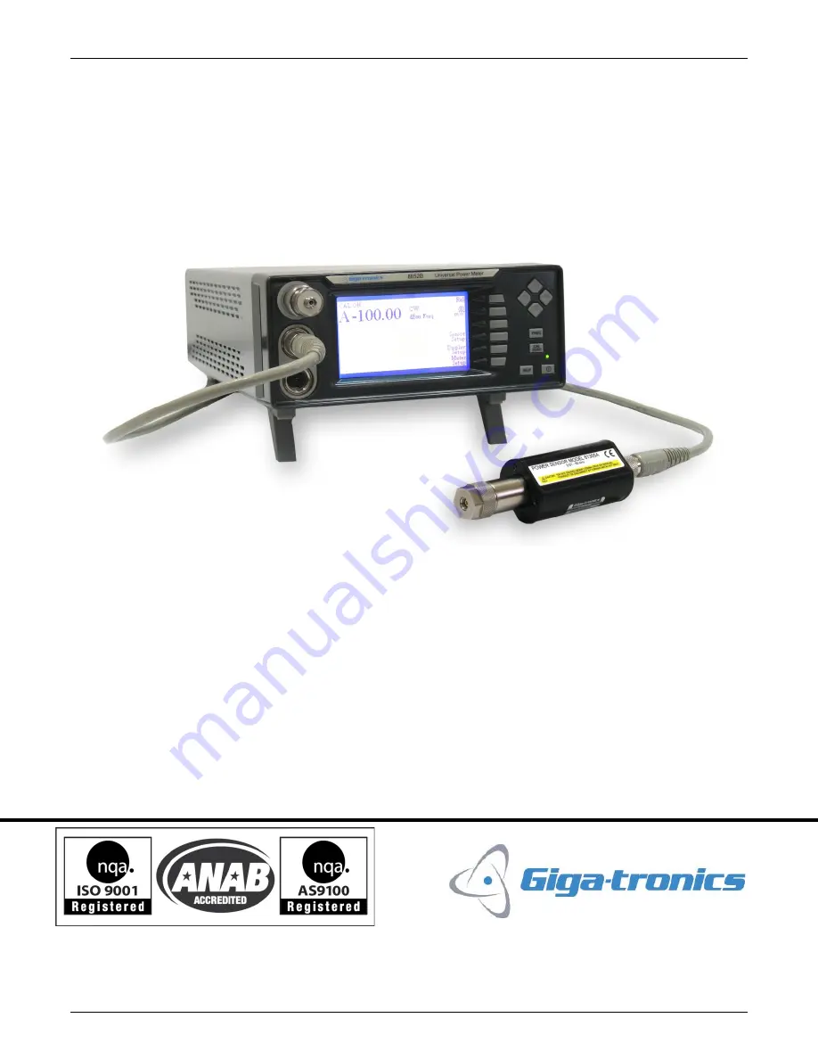
Series 8650B Universal Power Meters 


Publication 31470-001, Rev C, November 2, 2017 


Series 8650B Universal Power Meters 

Operation Manual 

Giga-tronics Incorporated 

 4650 Norris Canyon Road, San Ramon, CA 94583 

925.328.4650/800.726.4442/925.328.4700 (Fax) 

Customer Service: 800.444.2878/925.328.4702 (Fax)


Содержание 8650B Series

Страница 1: ...on 31470 001 Rev C November 2 2017 Series 8650B Universal Power Meters Operation Manual Giga tronics Incorporated 4650 Norris Canyon Road San Ramon CA 94583 925 328 4650 800 726 4442 925 328 4700 Fax Customer Service 800 444 2878 925 328 4702 Fax ...

Страница 2: ...rved Printed in the USA WARRANTY Giga tronics Series 8650B instruments are warranted against defective materials and workmanship for one year from date of shipment Giga tronics will at its option repair or replace products that are proven defective during the warranty period This warranty DOES NOT cover damage resulting from improper use nor workmanship other than Giga tronics service There is no ...

Страница 3: ...Series 8650B Universal Power Meters Publication 31470 001 Rev C November 2 2017 iii ...

Страница 4: ...nt s front panel keys display and configuration menus 3 Remote Operation A guide to the instrument s remote control interface 4 Performance Verification Defines the procedures to verify the performance of the 8650B Meter Appendices A Typical Applications Programs Provides examples of programs for controlling the 8650B remotely B Power Sensors Provides selection data specifications and calibration ...

Страница 5: ...ocedure or practice which if not strictly corrected or observed could result in injury or death of personnel An example is the proximity of high voltage Caution CAUTION The CAUTION statement is enclosed with single lines and centered in the page This calls attention to a situation or an operating or maintenance procedure or practice which if not strictly corrected or observed could result in tempo...

Страница 6: ... convenience to maintain a permanent record of publication change data Corrected replacement pages will be issued as TPCI Technical Publication Change Instructions and will be inserted at the front of the binder Remove the corresponding old pages insert the new pages and record the changes here TPCI Number TPCI Issue Date Date Entered Comments ...

Страница 7: ...pecial Configurations When the accompanying product has been configured for user specific application s supplemental pages will be inserted at the front of the publication binder Remove the indicated page s and replace it them with the furnished Special Configuration supplemental page s ...

Страница 8: ...4 2 Inputs Outputs 1 6 1 2 4 3 Remote Interface 1 6 1 3 Specifications 1 7 1 3 1 Power Meter 1 7 1 3 2 Accuracy 1 8 1 3 3 Measurement Rates 1 11 1 3 4 Remote Operation 1 12 1 3 5 GPIB Fast Buffered Mode Controls 1 12 1 3 6 Inputs Outputs 1 12 1 3 7 General Specifications 1 13 1 3 8 Options 1 13 1 3 9 Power Sensors 1 13 CHAPTER 2 FRONT PANEL OPERATION 2 1 2 1 Introduction 2 1 2 2 Front Panel Descri...

Страница 9: ...ictions 2 33 2 4 10 When to use CW MAP BAP 2 33 2 4 11 Multi Tone Tests 2 33 2 4 12 Peak Hold 2 35 2 4 13 Crest Factor 2 36 2 4 14 Burst Signal Measurements 2 38 2 4 15 Burst Start Exclude Burst End Exclude 2 39 2 4 16 Burst Dropout 2 40 2 4 17 Optimizing Measurement Speed 2 41 2 4 18 Peak Power Measurements 2 42 2 4 19 Measuring an Attenuator Single Channel Method 2 42 2 4 20 Improving Accuracy 2...

Страница 10: ...21 3 2 12 Sensor Gate Commands 3 23 3 2 13 Reading Power Measurements 3 25 3 2 13 1 Special Errors 3 26 3 2 14 Instrument Triggering 3 27 3 2 15 Arming the Triggering Cycle 3 30 3 2 16 Channel Configuration 3 31 3 2 17 Cal Factor Correction 3 34 3 2 17 1 Cal Factor Error Control 3 35 3 2 18 High Speed Measurements 3 36 3 2 18 1 Operating Mode Control 3 36 3 2 18 2 Triggering Notes 3 38 3 2 18 3 Me...

Страница 11: ... 6 HP438 Emulation Command Code Set 3 78 3 4 Analog Output 3 80 3 4 1 Enabling Disabling the Output 3 80 3 4 2 Setting Options for the Output 3 80 3 5 Averaging 3 81 3 5 1 Auto Averaging 3 81 3 5 1 1 Activating the Auto Filter Mode 3 81 3 5 1 2 Setting the Measurement Settling Target 3 81 3 5 1 3 Freezing the Present Averaging Number 3 82 3 5 2 Manual Averaging 3 83 3 6 Cal Factors 3 84 3 7 Calibr...

Страница 12: ... 15 Limits 3 104 3 15 1 Setting Limits 3 104 3 15 2 Activating Limits 3 104 3 15 3 Measuring with Limits 3 105 3 16 Measurement Collection Modes Standard 3 106 3 16 1 Measurement Triggering 3 106 3 16 1 1 Trigger Hold TR0 3 106 3 16 1 2 Trigger Immediate TR1 3 106 3 16 1 3 Trigger Immediate with Full Averaging TR2 3 106 3 16 1 4 Free Run TR3 3 106 3 16 2 Group Execute Trigger 3 107 3 16 2 1 Group ...

Страница 13: ... Min Max Feature 3 120 3 19 4 2 Reading the Min Max Values 3 121 3 19 5 Offset Commands 3 121 3 19 5 1 Enabling Disabling an Offset 3 122 3 19 5 2 Setting an Offset Value 3 122 3 19 6 Measured Offset Entry 3 123 3 19 7 Peak Hold 3 124 3 19 7 1 Enabling the Peak Hold Feature 3 124 3 19 7 2 Reading the Peak Hold Value 3 124 3 19 8 Peak Power Sensor Commands 3 126 3 19 8 1 Series 80350A Peak Sensors ...

Страница 14: ...ator Output Power Reference Level 4 2 4 3 1 1 Procedure 4 2 4 3 2 Calibrator Frequency Check 4 4 4 4 Performance Verification Tests 4 4 4 4 1 Equipment Required 4 4 4 4 2 Instrument Plus Power Sensor Linearity 4 5 4 4 2 1 Test Description 4 5 4 4 2 2 Setup Parameters 4 6 4 4 2 3 Test Procedure 4 6 4 4 3 GPIB Port Check 4 7 APPENDIX A TYPICAL APPLICATIONS PROGRAMS A 1 A 1 Introduction A 1 A 2 Conti...

Страница 15: ...In Calibrator Out Connectors 8652B C 2 C 2 4 Option 05 Soft Carrying Case C 2 C 2 5 Option 07 Side mounted Carry Handle C 2 C 2 6 08 Transit Case C 2 C 2 7 Option 09 Dual Power Meter Rack Mount Kit C 2 C 2 8 Option 10 Assembled Dual Power Meter Rack Mount Kit C 2 C 2 9 Option 12 1 GHz 50 MHz Switchable Calibrator C 2 C 2 10 Option 13 Rear Panel Sensor In Connectors 8651B C 2 C 2 11 Option 14 Rear ...

Страница 16: ...ensor Calibration 2 24 Figure 2 15 Peaking Meter 2 27 Figure 2 16 Burst Measurement 2 29 Figure 2 17 Delay Delay Offsets 2 32 Figure 2 18 Peak Hold 2 35 Figure 2 19 Crest Factor 2 36 Figure 2 20 Burst Start Exclude Burst End Exclude 2 39 Figure 2 21 Burst Dropout 2 40 Figure 3 1 SCPI Subsystem Model 3 6 Figure 3 2 CALCulate Subsystem Commands 3 8 Figure 3 3 Additional CALCulate Subsystem Commands ...

Страница 17: ...vice Specific Error Messages 3 65 Table 3 10 8650B IEEE 488 2 Command Set 3 69 Table 3 11 8540C Emulation Command Set 3 72 Table 3 12 HP436 Emulation Command Set 3 75 Table 3 13 HP437 Emulation Command Set 3 76 Table 3 14 HP438 Emulation Command Set 3 78 Table 3 15 Measurement Setting Target Default Values 3 81 Table 3 16 Number Averaging 3 83 Table 3 17 Learn Mode 1 Output Format 3 102 Table 3 18...

Страница 18: ......

Страница 19: ... and Series 813XXA Power Sensors See Option 12 in Appendix C 1 1 1 Features CW Peak and Modulation Power Meter with Burst Mask Testing More than 26 000 Readings Second in the Fast Buffered Mode GPIB only 90 dB Dynamic Range CW Sensors Sensor specific 0 3 Linearly per Degree Centigrade of Temperature Change True Dual Channel Display SCPI Command Modes GPIB USB and LAN Compatable with Measurement Xp...

Страница 20: ...l See Section 1 2 1 for details to set the voltage and install the correct fuse for the area in which the instrument will be used 1 1 4 Items Furnished In addition to options and or accessories specifically ordered items furnished with the instrument are Operation Manual P N 31470 001 Power Cord 1 ea Detachable Sensor Cable for Model 8651B 1 ea or Detachable Sensor Cables for Model 8652B 2 ea 1 1 ...

Страница 21: ...se the original shipping container If the original container is not available use a strong carton 350 lbs sq in bursting strength or a wooden box Wrap the instrument in heavy paper or plastic before placing it in the shipping container Completely fill the areas on all sides of the instrument with packaging material Take extra precaution to protect the front and rear panels Seal the package with st...

Страница 22: ...erating voltage and fuse rating have been checked The instrument can be damaged if connected to a source voltage with the line voltage selector set incorrectly 1 2 1 Safety Precautions The 8650B has a 3 wire power cord with a 3 terminal polarized plug for connection to the power source and safety ground The ground or safety ground is connected directly to the chassis WARNING If a 3 to 2 wire adapt...

Страница 23: ... above the AC power connector on the rear panel To gain access to them use a small screwdriver or similar tool to snap open the cover and proceed as follows 1 To change the voltage setting Use the same tool to remove the voltage selector a small barrel shaped component marked with voltage settings Rotate the selector so that the desired voltage faces outward and replace the selector back in its sl...

Страница 24: ...ering and gating measurements as defined by the Gate Trigger menu selections or under remote control Maximum input without damage is 15 V VPROPF In Accepts a voltage input that is proportional to frequency and causes the 8650B to apply appropriate frequency related cal factors Maximum input without damage is 15 V Analog Out A B Each provides an output voltage that is proportional to the measured p...

Страница 25: ...ual 1 to 1024 readings Timed averaging from 20 ms to 20 seconds Automatic noise compensation in auto averaging mode dB Rel Offset Allows both relative and offset readings Power display can be offset by 99 999 dB to 99 999 dB to account for external loss gain Configuration Storage Registers Up to 20 front panel setups plus a last instrument state at power down to be stored and recalled from non vol...

Страница 26: ...arity Specifies the external signal TTL high or low level as true for defining the gated time 1 3 2 Accuracy 50 MHz Calibrator Standard Calibrator 20 to 30 dBm power sweep calibration signal to dynamically linearize the sensors Frequency 50 MHz Nominal 0 0 dBm Accuracy 1 2 worst case for one year over a temperature range of 5 to 35 C VSWR 1 05 Return Loss 33 dB 0 dBm Connector Type Type N 50 Ω 1 G...

Страница 27: ...Linearity 0 02 dB over any 20 dB range from 70 to 16 dBm1 0 02 dB 0 05 dB dB from 16 to 20 dBm System Linearity 50 MHz 0 04 dB from 70 to 16 dBm The following chart shows linearity plus worst case zero set and noise vs input power Instrumentation Linearity continued Temperature Coefficient of Linearity 0 3 C temperature change following Power Sweep calibration 24 hour warm up required Zeroing Accu...

Страница 28: ...warm up at constant temperature 3 Measurable over any 1 minute interval after zeroing three standard deviations 4 Measurable over any 1 hour interval after zeroing three standard deviations Zero Drift Measurement a Set the meters Average to 1024 Perform Calibration Connect a 50 ohm load to the sensor after Calibration and Zeroing b Temperature stabilize at 25 C for 24 hours c After the 24 hour sta...

Страница 29: ...y after measurement in the Normal Freerun mode continuous single readings The Normal Freerun mode and the GPIB Swift Freerun mode both slow down at low power levels 37 dBm for Standard Sensors to average the effects of noise The GPIB Swift Buffered mode allows triggering of individual data points and can store the data in the 8650B memory Measurement speed increases significantly using the 8650B G...

Страница 30: ...ate to 5 typical 1 3 6 Inputs Outputs VPROPF Input BNC Recalls cal factors using source VPROPF output Corrects power readings for sensor frequency response using sweeper voltage output Input resistance 50K Does not operate in the fast measurement collection modes normal mode only Analog Output A B BNC Two configureable outputs that provide an output voltage of 0 to 10V from either Channel A or Cha...

Страница 31: ...t using RS 232 format 1 3 7 General Specifications Temperature Range Operating 0 to 55 C 32 to 132 F Storage 40 to 70 C 40 to 158 F Power Requirements 100 120 220 240Vac 100 pW 10 48 to 440 Hz 20 VA typical Physical Characteristics Dimensions 215 mm 8 4 in wide 89 mm 3 5 in high 368 mm 14 5 in deep Weight 4 55 kg 10 lbs 1 3 8 Options Refer to Appendix C for descriptions of options 1 3 9 Power Sens...

Страница 32: ......

Страница 33: ... Purpose Interface Bus USB Universal Serial Bus LAN Local Area Network and RS 232 serial communication devices This chapter contains the following major sections Front Panel Description Front Panel Applications Measurement Guide 2 2 Front Panel Description Although the Series 8650B has different modes of operation the front panel is simple in design and easy to use The instrument is configured and...

Страница 34: ...ey specifies the frequency of an input signal so that the power meter can apply the frequency specific cal factor from the sensor EEPROM to the measurement If the frequency of the input signal changes so often that it is impractical to keep entering the frequency with the FREQ key the frequency information can be conveyed to the 8650B by the use of a voltage input that is proportional to frequency...

Страница 35: ...keys The menus to calibrate and perform measurements with the 8650B are many and varied A complete menu map is provided in Appendix D of this publication Until thoroughly familiar with the operation of the 8650B refer to the appropriate menu map to reach the function to perform in order to speed up operation When turning on the power the model number and software version will display for five seco...

Страница 36: ... for configuring the display See Section 2 3 2 Sensor Setup for configuring installed sensors See Section 2 3 4 dB mW for selecting dB or power as the measurement unit See below Reset Menu to refresh a min max value See below Rel for recording Relative Measurements See Section 2 3 3 Figure 2 2 Main Menu From the Main Menu press dB mW at any time to toggle between dB and mW as the measurement units...

Страница 37: ... output as an RF source indicated by the words CAL ON in the upper left corner of the Main Menu See Figure 2 2 Turn on the 8650B for 15 minutes then cycle the power OFF and ON this establishes the 1 mW reference for the instrument firmware To turn the Calibrator ON or OFF press Meter Setup from the Main menu This will display the Meter Setup menu From the Meter Setup menu press Calibrator to displ...

Страница 38: ...the 8650B over the GPIB interface 1 From the Power Meter Configuration menu move the cursor to the GPIB option and press Config The menu to set the GPIB mode and address will display 2 Press Mode to highlight the operating mode and use the cursor keys to select the desired mode of operation The options are SCPI to use the SCPI IEEE 488 command set 8600 to use the IEEE 488 2 8650 native mode 8542 t...

Страница 39: ...OK to accept the changes or Cancel to cancel the changes and return to the Power Meter Configuration menu Analog Out A Analog Out B The Analog A and B outputs are voltage proportional to measured power that can be applied to auxiliary test equipment such as a data recorder From the Power Meter Configuration menu move the cursor to the Analog Out A or Analog Out B option and press Config The Analog...

Страница 40: ... cursor to the Strip Chart option and press Config See Figure 2 4 2 Press Select Source The choices for measuring sources are Lines 1 through 4 If any line is set for data gathering it will not be displayed here 3 Press Sample Rate The choices are from 1 sample per minute to 5 samples per second 4 Toggle between Hold Bfr to stop sampling when the buffer is full or Rot Bfr to set the Strip Chart di...

Страница 41: ...Power Meter Configuration menu move the cursor to the RS 232 option and press Config The RS 232 Config menu will display for configuration of the RS 232 interface 1 Press Baud to set the Baud Rate Select the desired rate with the up down cursor keys The default value is 9600 2 Press Length to set the Data Bits Select the desired data bit length with the up down cursor keys The default value is 8 3...

Страница 42: ...llustration 1 From the Power Meter Configuration menu move the cursor to the T Gate option and press Config to display the Gate Trigger menu 2 From the Gate Trigger menu select the sensor with the cursor keys and then select the mode of gated operation for that sensor The options are External Gate External Trigger Rising External Trigger Falling and Burst Edge a Gate This configures the gate to me...

Страница 43: ...hen an external trigger is input Point A in Figure 2 6 it starts the Trigger Delay At the end of the Trigger Delay the Gated Time measurement starts and lasts until its preselected time expires The Holdoff Time then prevents any further trigger inputs such as Point B below from starting a new gated measurement until it has timed out Figure 2 6 External Triggering Illustration ...

Страница 44: ...m of approximately 10 µs per displayed point 2 Select Delay and set its value with the cursor keys The range is 0 µs to 100 ms 3 Select Gate Time and set its value with the cursor keys The range is 5 µs to 100 ms 4 Select Holdoff and set its value with the cursor keys The range is 0 µs to 100 ms 5 Press OK to accept the changes or Cancel to cancel the changes and return to the Power Meter Configur...

Страница 45: ...e Histogram will display full screen as shown in Figure 2 8 Figure 2 8 Histogram Illustration There are additional functions available from the Histogram screen 1 Press Reset to restart sampling 2 Press Select Mode to toggle between distribution display functions a The Histogram See Figure 2 8 shows the percentage of time each power level is measured b The CDF Cumulative Distribution Function show...

Страница 46: ...on of the Ethernet interface 2 Press DHCP to set the Dynamic Host Configuration Protocol Select ON OFF with the up down cursor keys The default value is ON which will automatically assign an IP address to the 8650B To automatically assign an IP address turn DHCP ON and press OK Note If DHCP is enabled and a valid DHCP server is not available a short period of unresponsiveness may be experienced wh...

Страница 47: ...set to recall the default setup for the connected sensors Store 1 To store the current configuration press Sto Rcl from the Meter Setup menu 2 Select Store to store the current setup 3 Select the setup ID 1 through 20 to assign to this setup 4 A name of up to 16 characters can be used as an additional means of identifying the setup Press Name to open the display containing this option Set the name...

Страница 48: ...peaking meter bar graph when configured for use In addition the control to set the screen brightness is included in this display other Options One to four lines of data can be configured and any attached sensor can be mapped to any of the four lines Other information items are displayed at the top of the screen These include CAL ON which displays whenever the calibration RF source is on REMOTE whi...

Страница 49: ...change to Min Max Configure the selected line number to be the source For example use the selected line to display the minimum maximum values of another line Line n The only line numbers that will be available for selection are those which have already been configured and are not configured to show min max values of other lines If selecting line number to show the min max values of another line bu...

Страница 50: ...tics can be configured only for Resolution the Set Limits and Bar Graph options will not display for these lines 1 Press Config and use the cursor keys to set the Resolution of the input The resolution will be displayed in the large window at the bottom of the screen Adjust the resolution with the cursor keys to the desired level The range is 0 to 3 decimal places 2 Press Set Limits to set the upp...

Страница 51: ...changes 2 3 3 Relative Mode Rel Normally each line of the display shows a sensor measurement value When pressing Rel from the Main menu the present measured value of each line is recorded and all subsequent measurements are expressed in dB or percentage relative to that recorded value The Relative Measurement menu provides a means of selectively enabling or disabling the relative measurement mode ...

Страница 52: ...etup menu to display the Averaging menu This menu offers three options Auto Averages and Time Auto 1 Select this setup option if the time is to be adaptive averaged That is the time window changes dynamically to reduce the effects of transient changes in power levels 2 Press OK to store the changes or Cancel to exit without saving changes Averages 1 Select this setup option to set the number of pe...

Страница 53: ...l Trigger mode a Internal Trigger Peak power will be sampled at a point defined by a Trigger Level a Delay and a Delay Offset Refer to Section 2 4 8 2 for details of these Peak mode parameters The delay offset feature is a convenience in some applications For example when measuring pulse width from a point other than the trigger level or when comparing the levels of various pulses within a pulse t...

Страница 54: ...se average inputs Use the cursor keys to adjust the Duty Cycle The range is 0 001 to 99 999 d Press BAP to select the BAP mode The options are Auto Config and User Config 1 Press Auto Config for the meter to automatically configure itself and return to the Sensor Setup menu 2 Press User Config to configure the meter manually A prompting will occur to enter the values for the Burst Start Exclude Bu...

Страница 55: ...ensor This is done to keep the RF signal out of the base band signal processing circuitry When a 807XXA sensor is calibrated on the meter for the first time the meter reads UNCALIBRATED before calibration the unit is set to the default setting of MAP mode with frequency correction set to 1 GHz This allows the sensor to measure signals with wide bandwidth modulation For frequencies of 200 MHz or be...

Страница 56: ... 5 C to 35 C 41 to 95 F operating temperature range of the Calibrator Figure 2 14 Setup for Sensor Calibration 3 Press the CAL ZERO hardkey The meter will automatically zero and calibrate the sensor A sensor requires several minutes to fully zero and calibrate After the zero calibration routine is complete the display will return to the Main menu NOTE If the calibrator is set to 0 00 dBm and turne...

Страница 57: ...ce during zeroing By turning off the source instead of disconnecting the detector the zeroing process automatically accounts for ground line voltages and connector interface EMF NOTE Sufficient time must be allowed for the module to reach thermal equilibrium with the source This could be up to 15 minutes for moderate initial temperature differences 2 4 3 3 Calibration Zeroing High Power Sensors wi...

Страница 58: ...lidation of meter and sensor noise floor will be checked using an attenuator or termination Connect the attenuator or termination to the sensor and allow the unit to stabilize for 3 minutes The sensor must be thermally stabilized for proper zeroing If the thermal condition of the sensor varies during the zero procedure the zero will not be valid 4 Set averaging to 1024 and configure for CW operati...

Страница 59: ...50 dB CW Entering the operating frequency enables the 8650B to automatically apply frequency calibration factors appropriate to the sensor being used The operating frequency can be communicated to the 8650B using the front panel menus remotely or the VPROPF voltage input 2 4 5 Using the Peaking Meter The line bar graph provides a linear display of power level on a decade range basis For example a ...

Страница 60: ...ures three modulated measurement modes Modulated Average Power MAP Pulse Average Power PAP Burst Average Power BAP MAP and PAP modes measure the true average power of modulated and pulsed signals PAP mode differs from MAP mode only in that it allows specifying a duty cycle figure which is automatically factored into the measurement In BAP mode the true average power within the pulse is measured th...

Страница 61: ... rise time or fall time inaccuracy of the duty cycle or deviation from a flat pulse response will cause errors in the indicated reading 2 4 7 3 BAP Mode The Burst Average Power BAP mode measures the average power during an RF burst See Figure 2 16 This mode is very useful for measurement of pulse modulated signals which are not flat or have amplitude modulation during the pulse ON period as in the...

Страница 62: ...he average power in the pulse or burst As with the PAP mode when measuring a pulse modulated signal with 50 duty cycle the reading in the BAP mode would be 3 dB higher than in the MAP mode However in the BAP mode the signal s duty cycle can change dynamically in time without affecting the meter reading In the PAP mode the duty cycle factor must be entered to match the duty cycle of the pulsed sign...

Страница 63: ...by various factors The maximum settling time is equal to 20 ms multiplied by the averaging factor for example if the averaging factor is 128 the maximum settling time is 2 56 seconds In most situations the actual settling time is well below the maximum 2 4 8 2 PEAK Mode 80350A Peak Power Sensor The Peak mode is for instantaneous peak measurements of the RF power level of a pulse modulated signal d...

Страница 64: ...ined by the user To this delay can be added a positive or negative delay offset The delay offset is not necessary for peak measurement but in some applications it is a convenience For example a small offset even a negative offset might compensate for the difference between the trigger point and some other point of interest such as the half power point especially in applications where pulse width i...

Страница 65: ...l regardless of modulation type See Section B 2 2 for limits on modulation rate etc CW signals may also be accurately measured in MAP mode CW mode offers a few more dB of dynamic range at low power levels when using a CW power sensor such as the 80301A In addition in CW mode the 8650B s form fit and function are compatible with its predecessor the 8540 BAP mode should be used only for the measurem...

Страница 66: ...iple carriers In determining expected measurement error for these types of signals the maximum difference in frequency between any two carriers should be used as the tone separation when applying the error charts in the manual Another important feature of multi carrier signals is that they can have a high peak to average power ratio This ratio can be as high as 10 dB for multiple carriers The sign...

Страница 67: ...ted to increase accuracy and maintain wide bandwidth of Peak Hold measurement over the peak power range of 20 dBm to 20 dBm The Peak Hold selection will also affect Histogram measurement if there is power below 20 dBm To obtain accurate average power measurements below 20 dBm remove the display line containing Peak Hold or in remote control send the command which disables the Peak Hold feature The...

Страница 68: ...pressing Reset Line n of the appropriate line or in remote control by sending the command which activates the Crest Factor feature See Section 3 8 In Figure 2 19 the same power input trace is used in two graphs to illustrate the effect of a drop in average power with and without a reset In the top graph the power drop is followed by a reset The held value drops to the current measured value and th...

Страница 69: ...d maintain wide bandwidth of Crest Factor measurement over the peak power range of 20 dBm to 20 dBm The Crest Factor selection will also affect Histogram measurement if there is power below 20 dBm To obtain accurate average power measurements below 20 dBm remove the display line containing Crest Factor or in remote control send the command which disables the Crest Factor feature NOTE Reset Line n ...

Страница 70: ...r the operating carrier frequency 4 Connect the sensor to the burst signal source and record the power level The 8650B will automatically find the portions of the signal which are in the burst and include only those portions in the average Burst signals can have a high peak power to average power ratio depending on duty cycle This ratio is proportional to the duty cycle and is given by This assume...

Страница 71: ...xcluded periods overlap there is nothing left of the burst to be measured If the entire burst is excluded NoSync will flash on the screen to the right of the sensor power units and the meter will revert to average measurement in the style of the MAP mode The start exclude time is selected from a series of discrete values from 0 000 ms to 45 548 ms in increments of 0 027 ms The end exclude time has...

Страница 72: ...uring the burst have a duration of less than 350 µs therefore the entire burst is interpreted as a single burst and the dropouts are included in the average power measurement The 3 5 ms OFF period following the burst is interpreted as the end of the burst because it exceeds 350 µs in duration This feature must be configured and interpreted with care The dropout time is selected from a series of di...

Страница 73: ...uto average algorithm will specify an averaging time just long enough so that the result put on the bus is within 0 5 that is 0 02 dB of the average power Thus the settled measurement data is available on the bus in the minimum time necessary to be within the specified tolerance The tolerance specified in the FA command is a target tolerance For example it is possible that the peak to peak power v...

Страница 74: ...nternal or external triggering 7 Connect the peak power sensor s Detector Out to an oscilloscope to view the sample position For 80350A Peak Power Sensors also connect the sensor s Sample Delay output to the oscilloscope and trigger on that channel 2 4 19 Measuring an Attenuator Single Channel Method Attenuators are useful for many applications With the 8650B attenuators can be calibrated quickly ...

Страница 75: ...ong the transmission line At various points along the transmission line the standing wave will be at maximum or minimum amplitude Mismatch uncertainty is a measure of the deviation between these amplitude levels Inserting an attenuator into the transmission line reduces mismatch uncertainty by reducing the amplitude of the reflected signal thereby reducing the difference between a standing wave s ...

Страница 76: ... uncertainty 2 Connect the reference standard power meter to power splitter output X and the power meter to be verified to splitter output Y 3 Adjust the source frequency to a standard reference frequency 50 MHz for 803XXA 804XXA and 806XXA series sensors or 1 GHz for 813XXA and 807XXA series sensors 4 Enter the operating frequency or frequency cal factors into the power meters 5 Adjust the source...

Страница 77: ...ade signal source Power splitter output tracking errors are the maximum signal level variation at the splitter X output as compared to the splitter Y output Total measurement uncertainty for each of the power meters is the worst case combination of mismatch uncertainty instrument accuracy and sensor accuracy Mismatch uncertainty is calculated from the reflection coefficients of the sensor and the ...

Страница 78: ......

Страница 79: ...st SR1 complete capability Remote Local RL1 complete capability Parallel Poll PP1 remote configuration Device Clear DC1 complete capability Device Trigger DT1 complete capability Controller C0 no capability 3 1 1 Sending Commands to the 8650B over GPIB The 8650B power meter uses standard protocols for communication over the GPIB Commands conform to IEEE 488 1 or IEEE 488 2 guidelines Four emulatio...

Страница 80: ...13 places the 8650B into the local control mode The interface command REMOTE 713 places the 8650B into the remote control mode Enter LOCAL 713 to return the instrument to local mode The interface command LOCAL LOCKOUT 7 places the 8650B in the local lockout mode This is a remote control mode in which all of the 8650B front panel keys are disabled The GPIB LOCAL command must be issued to return the...

Страница 81: ...te 1 stay here until zero done State PPOLL 7 read the poll END WHILE PPOLL UNCONFIGURE 713 cancel parallel poll mode PRINT parallel zero done RETURN 3 1 2 2 Serial Polling over GPIB Srq_zero zero with an srq interrupt PRINT entering SRQ interrupt zero routine ON INTR 7 GOSUB Srq_interrupt OUTPUT 713 CS clear status byte ENABLE INTR 7 2 enable srq interrupts OUTPUT 713 1 CHR 2 enable srq handshake ...

Страница 82: ...t Buffered modes are expressed in the form of a signed five digit number with two digits to the right of the decimal and no exponents In some cases multiple values are sent One sensor Swift mode DDD DD CRLF Two sensor Swift mode DDD DD DDD DD CRLF Fast Buffered mode DDD DD DDD DD CRLF 3 1 4 Power On Default Conditions The interface wake up state is GPIB Local Mode Unaddressed Service Request Mask ...

Страница 83: ...ote the generated IP address in the Information screen when the configuration is complete This IP address will be used for instrument connection 4 LAN configuration is complete 3 1 5 3 USB Configure the 8650B for remote operation over USB 1 Select the interface command mode 8600 or SCPI under the Mode selction of the GPIB Configuration menu see Section 2 3 1 2 for details 2 Connect the 8650B to th...

Страница 84: ... a signal that passes through an attenuator or coupler before it is measured by power Sensor2 Figure 3 1 illustrates the SCPI subsystem model NOTE Throughout this publication some commands will be in both upper and lowercase such as CALCulate and MEMory The uppercase is the required input The whole word can be used if desired If the whole word is used it must be used in its entirety For example CA...

Страница 85: ...ices The VPROPF can be configured to match the VPROPF output of the microwave source The analog outputs are used with a variety of devices including chart recorders oscilloscopes voltmeters and microwave source leveling inputs 3 2 5 IEEE 488 2 Required Commands Consistent with SCPI compliance criteria the power meter implements all the common commands declared mandatory by IEEE 488 2 See Table 3 2...

Страница 86: ...he number of violations and allow the violation counter to be cleared The REFerence command allows channel based offset values For example using CALC REF COLL automatically converts the inverse of the current channel measurement value to an offset simplifying the 1 dB compression testing of amplifiers MIN and MAX commands monitor deviation of measured values over a user controllable time period Th...

Страница 87: ...Remote Operation Publication 31470 001 Rev C November 2 2017 3 9 Figure 3 3 Additional CALCulate Subsystem Commands Modulation Sensors ...

Страница 88: ...pplies sensor specific Calibration Factor corrections which compensates for sensor frequency response characteristics Controlling Peak Power Sensor triggering Controlling Modulation Power Sensors SENSe subsystem commands control functions that are related directly to the individual power sensors For example these commands control items that would not apply to numerical alteration of a ratio measur...

Страница 89: ...commands are not instrument triggers but Peak Power Sensor configuration controls SENSe TRIGger functions apply only to Giga tronics Peak Power Sensors The DELay and LEVel functions of these Peak Power Sensor controls apply to the 8035XA Peak Power Sensors The AVERage and CORRection commands apply to all 803XXA Series CW Peak Power Sensors ...

Страница 90: ...nformation following command errors which are commonly caused by using illegal configuration commands during GPIB Swift or GPIB Burst modes SOURce IMMediate triggering allows the 8650B to control measurement triggering this is the default configuration EXTernal triggering is performed using a TTL signal input BUS allows software controlled triggering COUNt refers to the number of data points to st...

Страница 91: ...ion Publication 31470 001 Rev C November 2 2017 3 13 Figure 3 6 SENSe Subsystem Command Tree for Configuring Modulation Sensors Figure 3 7 SENSe Subsystem Command Tree for Configuring Modulation Sensor Gate Settings ...

Страница 92: ...lues or mnemonics valid for that parameter are enclosed in angle brackets 3 2 9 3 Italics in Syntax Descriptions Some command syntax descriptions show certain words in italics such as space and comma to indicate where the character must be included within a command string 3 2 9 4 Query Format Except where specifically noted all query commands are formed by adding a question mark to the command hea...

Страница 93: ...DATA Interrupts the Burst measurement and dumps the measurement data 3 2 18 CALCulate channel 1 to 4 FUNCtion Query the channel configuration 3 2 16 CALCulate channel 1 to 4 LIMit CLEar IMMediate Reset the channel limit violation indicator to 0 3 2 26 CALCulate channel 1 to 4 LIMit FCOunt Query the channel for number of limit failures 3 2 26 CALCulate channel 1 to 4 LIMit FAIL Query the channel fo...

Страница 94: ...strument triggering cycle 3 2 15 INITiate CONTinuousspace ON OFF Enable Disable the continuous instrument triggering cycle reset 3 2 15 MEASure channel 1 to 4 SCALar POWer Initiate trigger and return the channel measurement data 3 2 13 MEMory TABLe CHANnelspace channel 1 or 2 Set the active Analog Output channel 3 2 27 MEMory TABLe FREQuency start frequency Set the VPROPF correction start frequenc...

Страница 95: ...11 SENSe sensor 1 or 2 CORRection EEPROM TYPE Query the sensor eeprom type 3 2 34 SENSe sensor 1 or 2 CORRection EEPROM FREQuency Query the sensor eeprom frequency table 3 2 34 SENSe sensor 1 or 2 CORRection EEPROM CALFactor Query the sensor eeprom cal factor table 3 2 34 SENSe sensor 1 or 2 CORRection FREQuency CW FIXed space frequency in Hz Set the sensor compensation frequency 3 2 17 SENSe sens...

Страница 96: ...us register values 3 2 31 SYSTem COMMunicate SERial RECeive BAUDspace baud rate Set the receive baud rate 3 2 23 SYSTem COMMunicate SERial TRANsmit BAUDspace baud rate Set the transmit baud rate 3 2 23 SYSTem ERRor Query the system error message 3 2 36 SYSTem LANGuage NATIVE Switch to native language 8600 3 2 30 SYSTem PRESet Reset 8650B configuration 3 2 31 SYSTem VERSion Query SCPI version 3 2 3...

Страница 97: ...wer 15 dB of a sensor s dynamic range For standard sensors this is 55 dBm CALibrate Syntax CALibration sensor 1 or 2 SENSor Example CAL1 CALIBRATE SENSOR 1 Description This command begins the sensor power sweep calibration process Power sweep calibration can be performed only during Normal mode The sensor must be attached to the front panel CALIBRATOR use an adapter for high frequency sensors with...

Страница 98: ...or If disabling the signal source cannot occur connect the sensor to a grounded connector preferably RF grounded or leave the sensor disconnected Do not connect the sensor to the power meter front panel calibrator port If the meter detects excessive RF power at the start of the zeroing process generally above 50 dBm for standard sensors zeroing will automatically fail SENSe TEMP Syntax SENSe senso...

Страница 99: ...sensor 1 or 2 CONFig MAP SYNChronized Example SENS1 CONF MAP ENABLES SYNCHRONIZED MAP MODE FOR SENSOR 1 Description Configures a modulation sensor for Synchronized MAP Modulated Average Power mode on the specified input SENSe CONFig MAP UNSYnchronized Syntax SENSe sensor 1 or 2 CONFig MAP UNSYnchronized Example SENS1 CONF MAP UNSY ENABLES UNSYNCHRONIZED MAP MODE FOR SENSOR 1 Description Configures...

Страница 100: ...NF BAP BSEX READS THE NUMBER OF BURST START EXCLUDE SAMPLES Description Sets the number of burst start exclude samples The timing for each sample is approximately 27 μs Syntax SENSe sensor 1 or 2 CONFig BAP BDTolerancespace dropout Where dropout is the dropout time in milliseconds in the range of 0 to 3 4 and with a resolution of 0 001 ms The system selects the nearest value from a series of discr...

Страница 101: ...initiates the trigger cycle After the set Gate Delay time has been satisfied the meter proceeds to measure the average power of a signal for the duration specified in by the Gate Duration setting In EDGE mode the meter internally detects the rising edge of a pulsed signal to trigger a gated measurement After the set Gate Delay time has been satisfied the meter proceeds to measure the average power...

Страница 102: ...1 µs Example SENS1 GATE DUR 250E 3 SETS THE SENSOR 1 TIME GATE DURATION TO 250 µS Example 2 SENS1 GATE DUR REQUESTS SENSOR 1 TIME GATE DURATION SETTING Description Sets the sensor Time Gate Duration in seconds which specifies the duration of the gating period This parameter is relavent only for TRIGGER and EDGE mode Query form for sensor Time Gate Duration command is available Response is gate dur...

Страница 103: ... mode is used for reading channel 1 and or channel 2 multi element array data from the meter s data buffer For example if channel 1 is defined as Sensor 1 and channel 2 is defined as Sensor 2 then In NORMal mode the FETCh1 query command will return the power level incident upon Sensor 1 and the FETCh2 query command will return the power level incident upon Sensor 2 In SWIFt mode with TRIG COUNt1 t...

Страница 104: ...ake measurements using sensor A or B or both but measurements such as A B and A B are not permitted In the remote normal collection mode only one reading can be sent over the bus it can be A or B or a comparative measurement such as A B but it is not possible for separate measurements of A and B to be sent over the bus The exception is that in the GPIB Swift and GPIB Burst measurement collection m...

Страница 105: ...eeded with INITiate IMMediate or FETCh when preceeded with INITitiate CONTinuous ON TRIGger SOURce IMMediate triggering is not compatible with the GPIB BURSt and GPIB SWIFt modes If sending the CALC MODE BURS command to enter GPIB BURSt mode the instrument TRIGger SOURce will automatically be switched from IMMediate to BUS If sending the CALC MODE SWIF command to enter GPIB SWIFt mode the instrume...

Страница 106: ...riggering and operating mode compatibility Operating Mode IMM BUS HOLD EXT NORMal X X X SWIFt X X X BURSt X X If the power meter has been configured for EXTernal triggering in the BURSt or SWIFt modes and the operating mode is switched to NORMal the triggering configuration remains EXT However if the configuration is IMM in NORMal mode and the meter is switched to BURSt it automatically switches t...

Страница 107: ...RSt modes this command controls the number of power readings that are stored in the 8650B data buffer The value specified here applies to each individual channel That is if two sensors are attached and calibrated the 8652B will perform the specified measurement and buffering for both channels In the example shown above for this command that would be 100 points per channel The 8650B controls its ga...

Страница 108: ...ent cycle set this control to OFF and use MEAS or INIT with READ to perform the measurement Another legal measurement control option would be INIT with TRIG and FETC when in TRIG SOUR BUS mode When INITiate CONTinuous is ON the instrument triggering cycle resets continuously That is upon instrument triggering data is constantly being acquired and updated Upon completion of a trigger cycle the mete...

Страница 109: ...NFIGURES CHANNEL 4 TO MEASURE THE RATIO OF SENSOR 2 OVER SENSOR 1 POWER Description This command configures a channel as a ratio of the power levels present at the two sensors When UNITs are DBM RATio configuration produces measurements in dB When UNITs are Watts RATio configuration measurements are percentage This command does not have a query format For the above example the response to a CALC1 ...

Страница 110: ...el 1 to 4 STATespace ON OFF Example CALC1 STAT OFF DISABLES CHANNEL 1 MEASUREMENT Example 2 CALC1 STAT QUERIES CHANNEL 1 MEASUREMENT STATUS Description This command turns a specified channel ON or OFF For a single channel meter Channel 1 is default ON For a dual channel meter Channel 1 and Channel 2 are default ON During NORMal mode measurement speed increases when only one sensor is performing me...

Страница 111: ...HOLD MEASUREMENT Description Reads the Peak Hold measurement from the specified display channel The Peak Hold function monitors the maximum power as it is measured but does not provide any feedback to the controller until the Peak Hold query command is received CALCulate StatisicalFUNctions STATe Syntax CALCulate channel 1 to 4 StatisticalFUNctions STATespace ON OFF Example CALC3 SFUN STAT ON ENAB...

Страница 112: ...ng SENSe CORRection FREQuency Syntax SENSe sensor 1 or 2 CORRection FREQuency CW FIXed space frequency in Hz Example SENS2 CORR FREQ 5E7 SETS SENSOR 2 FREQUENCY CORRECTION TO 50 MHZ Description This command sets the correction for sensor frequency response characteristics The power meter uses this specified frequency to automatically interpolate and apply the Cal Factor for that sensor computed fr...

Страница 113: ...20B Series Signal Generator this relationship is 0 5 V GHz or 5e 8 V Hz MEMory FREQuency Syntax MEMory TABLe FREQuencyspace Start frequency Example MEM FREQ 1E9 SETS VPROPF FREQUENCY TO 1 GHZ Description This command sets the automated VPROPF correction start frequency This is the frequency at which the voltage input into the 8650B is 0 0 V This is the second line required for configuring the VPRO...

Страница 114: ...p The BURSt mode remains active after this command so that a trigger will start a new measurement reference The command returns measurement data while the measurement is completing during BURSt mode only This command is not used in NORMal or SWIFt Modes Operation is similar to using FETCh Both are instrument not channel commands That is when both sensors are connected calibrated and the channel se...

Страница 115: ...01 second increments from 0 000 to 0 050 seconds inclusive Setting this control to 0 000 activates the highest reading rate possible for the particular measurement conditions Generally if the acquisition of individual data points with controlling triggering is required the GPIB SWIFt mode will provide the highest measurement rates with or without SRQ or hardware handshaking TRIGger COUNt Syntax TR...

Страница 116: ... operating modes proceed to send the required triggering configuration as well TRIGger SOURce EXTernal triggering is performed with the rear panel Trigger Input BNC connector and functions only in the GPIB BURSt and GPIB SWIFt modes EXTernal triggering is not available in the NORMal mode TRIGger SOURce BUS triggering sets the triggering control to the controller software using TRIG or TRG commands...

Страница 117: ...riggering is essentially disabled CW is automatically set by the 8650B during power sweep calibration do not apply any triggering to the peak power sensor during power sweep calibration Be sure to set the trigger level SENS TRIG LEV after the INTernal or EXTernal triggering is selected Syntax SENSe sensor 1 or 2 TRIGger DELay MAGnitude space delay in seconds from 50 5e 9 to 104 8e 3 Example SENS1 ...

Страница 118: ... trigger port on the back of the sensor housing is not 50 Ω it is a high impedance to prevent damage from triggering inputs such as 5 0 V TTL signals Using a high speed 50 Ω trigger source may cause unwanted signal reflections and noise on the trigger line An SMB to SMB attenuator is available from Giga tronics to alleviate this condition The attenuation reduces the reflected noise and reduces eli...

Страница 119: ...nt data is being repeatedly updated At high power levels measured minimum averaging is applied to optimize measurement speed As the power level drops additional averaging is applied to steady the measured data reading Syntax SENSe sensor 1 or 2 AVERage TCONtrolspace data acquisition averaging method MOVing or REPeat Example SENS1 AVER TCON REP SETS SENSOR 1 TO ACQUIRE FRESH MEASUREMENT DATA BEFORE...

Страница 120: ...HANNEL2 Description This command enables or disables the meter s level reference to give it the ability to perform relative measurements Syntax CALCulate channel 1 to 4 REFerence MAGnitude space dB Offset value from 299 999 to 299 999 Example CAL2 REF 30 11 SETS CHANNEL 2 REFERENCE OFFSET VALUE TO 30 11 DB Description This command sets the value to subtract from the channel measurement value This ...

Страница 121: ...ill automatically respond with the actual power level output in its measurement data SENSe CORRection Syntax SENSe sensor 1 or 2 CORRection OFFSet COLLect Example SENS1 CORR OFFS COLL TAKE SENSOR 1 CURRENT READING AS THE OFFSET VALUE Description This command enters the current power level reading as the offset value Syntax SENSe sensor 1 or 2 CORRection OFFSet MAGnitude space offset value in dB 99...

Страница 122: ... 2 SYST COMM SER REC BAUD QUERIES THE RECEIVE BAUD RATE Description Command modifies the receive baud rate for the RS 232 communications port to the specified baud rate Query form is available SYSTem COMMunicate SERial TRANsmit Syntax SYST COMMunicate SERial TRANsmit BAUDspace baud rate Where baud rate values are 50 75 110 134 5 150 200 300 600 1050 1200 1800 2000 2400 4800 7200 9600 19200 38400 7...

Страница 123: ...gisters The Status Byte Register STB and the Event Status Register ESR are required by the IEEE 488 2 standard The commands associated with IEEE 488 2 mandatory status registers are preceded by an asterisk An additional status register the Operation Status Register OPER STAT is implemented in the 8650B for added status monitoring ability Figure 3 9 details the SCPI status reporting model and shows...

Страница 124: ... certain events or conditions have occurred The Status Byte Register has an associated enable register The Service Request Enable Register SRE is effectively the enable mask of the Status Byte Register The Service Request Enable Register controls which bits in the Status Byte Register set the RQS bit bit 6 The Request Service bit RQS will in turn assert a Service Request SRQ A Service Request is g...

Страница 125: ... sending the Clear Status CLS command SRE Syntax SREspace binary weighted sum of all the bits to be enabled 0 to 255 Example SRE 32 SET BIT 5 25 OF THE SERVICE REQUEST ENABLE REGISTER Example 2 SRE QUERIES THE SERVICE REQUEST ENABLE REGISTER VALUE Description This command sets clears the Service Request Enable Register This is effectively the enable mask of the Status Byte Register The Service Req...

Страница 126: ...us Register will set the Event Status bit bit 5 of the Status Byte Register An occurance in the Event Status Register can therefore be set up to generate a Service Request with the use of the Event Status Enable Register and the use of the Service Request Enable Register set to enable the Event Status bit SRE 32 Table 3 5 SCPI Event Status Register Bit Weight Description Set Condition 0 1 Operatio...

Страница 127: ...e cleared by sending the Clear Status CLS command ESE Syntax ESEspace binary weighted sum of all the bits to be enabled 0 to 255 Example ESE 16 SET BIT 4 24 OF EVENT STATUS ENABLE REGISTER Example 2 ESE QUERIES THE EVENT STATUS ENABLE REGISTER VALUE Description This command sets clears the Event Status Enable Register This is effectively the enable mask of the Event Status Register The Event Statu...

Страница 128: ...effectively the enable mask of the Operation Status Register The Operation Status Enable Register controls which bits in the Operation Status Register will set the Operation Status bit bit 7 of the Status Byte Register An occurance in the Operation Status Register can therefore be set up to generate a Service Request with the use of the Operation Status Enable Register and the use of the Service R...

Страница 129: ...ction STATus OPERation ENABLe Syntax STATus OPERation ENABLespace binary weighted sum of all the bits to be enabled 0 to 65535 Example STAT OPER ENABL 32 SET BIT 5 25 OF OPERATION STATUS ENABLE REGISTER Example 2 STAT OPER ENABL QUERIES THE OPERATION STATUS ENABLE REGISTER VALUE Description This command sets clears the Operation Status Enable Register This is effectively the enable mask of the Ope...

Страница 130: ...ing bit in the Service Request Enable Register is set SRE 16 the status reporting structure will once again cause a Service Request to be generated OPC Syntax OPC Example OPC SET ESR OPC BIT WHEN OPERATION IS COMPLETE Description OPC determines when an operation is completed This command is generally used to monitor the completion of long measurement sequences It sets the Operation Complete bit OP...

Страница 131: ... OFF Example CALC2 MAX STAT ON ENABLES CHANNEL 2 MAXIMUM TRACKING Description This command enables and disables the MAXimum monitoring function on the specified channel The maximum value of the channel not sensor is monitored until the value is reset by CALC MAX STAT ON or CALC MAX STAT OFF is sent Syntax CALCulate channel 1 to 4 MAXimum MAGnitude Example CALC2 MAX QUERIES CHANNEL 2 MAXIMUM VALUE ...

Страница 132: ...omatically alert the controller directly during a limit violation the 8650B must be queried to receive information regarding pass fail status of limit line violations Automatic notification of limit line violations is accomplished using the status byte and the operation register A controller can be notified of a limit line violation via the request service SRE command After the controller receives...

Страница 133: ...PPerspace numeric value in dBm or dB from 299 99 to 299 99 Example CALC1 LIM UPP 17 0 SETS CHANNEL 1 UPPER LIMIT LINE TO 17 0 DBM Description This command specifies the upper limit line power level The value should allow for any offset values currently in use The default value is 299 99 dB or dBm Syntax CALCulate channel 1 to 4 LIMit STATespace ON OFF Example CALC1 LIM STAT ON ENABLES CHANNEL 1 UP...

Страница 134: ...utput A while channel 2 is always configured to Analog Output B Therefore if a particular output is required it may be necessary to first configure channel 1 or 2 using the appropriate channel configuration commands prior to configuring the Analog Output s MEMory SELect Syntax MEMory TABLe SELectspace ANALOGout VPROPF1 VPROPF2 Example MEM SEL ANALOG SELECTS MEMORY TABLE ANALOG FOR SUBSEQUENT ANALO...

Страница 135: ... be assigned corresponding voltages at the analog output If linear units are selected for analog output control this command selects the beginning and end points of the power levels in Watts which will be assigned corresponding voltages at the analog output This command must be preceded by the Analog Output units configuration MEMory UNIT MEMory VOLTage Syntax MEMory TABLe VOLTagespace start value...

Страница 136: ...are not listed under the RST or PRESet conditions are not savable Make sure all aspects of the configuration are savable For example sensor power sweep calibration curves can not be saved in the configuration memory registers Sensors must be calibrated to the 8650B power meter each time a new sensor is attached RCL Syntax RCLspace memory location number 0 to 20 Example RCL 19 RECALL 8650B REGISTER...

Страница 137: ...letion of the current action For example sensor calibration is not interrupted Burst mode data collection is not interrupted 3 2 30 Language Configuration SYSTem LANGuage NATIVE SYSTem LANGuage NATIVE Syntax SYSTem LANGuage NATIVE Example SYST LANG NATIVE SWITCHES ACTIVE GPIB COMMAND SET TO NATIVE LANGUAGE Description Command modifies the active GPIB command set to native 8600 from SCPI Query from...

Страница 138: ...VALUE Description This command resets the 8650B Status information buffers See Table 3 7 Note that these are not the power ON conditions SYSTem PRESet Syntax SYSTem PRESet Example SYST PRES RESET 8650B CONFIGURATION Description This command resets the 8650B configuration to a known condition SYST PRES is identical in function to RST Command Default Minimum Maximum Table 3 7 Reset Power On Default ...

Страница 139: ... 4e10 VPROpf STATe OFF OFFset STATe OFF MAGnitude 0 99 999 99 999 TRIGger SOURce CW LEVel MAGnitude 20 0 30 0 20 0 OFFSet MAGnitude 0 5e 8 104e 3 TOTAl MAGnitude 1e 6 5e 8 104e 3 DELay STATe ON MAGnitude 1e 6 5e 8 104e 3 TRIGger COUNt 1 0 5000 DELay 0 000 0 000 0 050 MODE POST SOURce IMMediate POWER ON will override the internal battery back up memory and reset only the following configuration ite...

Страница 140: ...e version Description The IDN is the identify query command defined by IEEE 488 2 Upon receipt of this command the power meter will output a string that identifies itself as the Giga tronics 8650B and indicates the instrument serial number and firmware version number SENS CORR EEPROM TYPE Syntax SENSe sensor 1 or 2 CORRection EEPROM TYPE Example SENS1 CORR EEPROM TYPE QUERIES SENSOR 1 EEPROM TYPE ...

Страница 141: ...eturns sensor model and serial number information This command allows programming to verify correct sensor usage and monitor whether power sweep calibration has been performed or not SENSe CORRection EEPROM FREQuency Syntax SENSe sensor 1 or 2 CORRection EEPROM FREQuency Example SENS1 CORR EEPROM FREQ QUERIES SENSOR 1 EEPROM FREQUENCY TABLE Response Typically 5 0000e7 2 0000e9 3 0000e9 Description...

Страница 142: ...prior to entering measurement configurations and measurement routines A listing of compatible standard SCPI error and device specific errors follows Table 3 8 SCPI Standard Error Messages Error Number Description 0 No Error 7 Invalid Error Number 105 GET Not Allowed 108 Parameter Not Allowed 111 Header Separator Error 113 Undefined Header 120 Numeric Data Error 130 Suffix Error 138 Suffix Not Allo...

Страница 143: ...ROM CORRection No valid sensor sensor eeprom data correction factor number does not match No sensor DIAGnostic SENSe1 EEPROM READ No valid sensor No sensor DIAGnostic SENSe1 EEPROM CALFSPecial DIAGnostic SENSe1 EEPROM CALFSTandard No valid sensor Sensor eeprom data is over space Sensor eeprom data cal factor number does not match No sensor Too much data DIAGnostic SENSe1 EEPROM FREQSTandard No val...

Страница 144: ...her table Lower voltage is greater than upper voltage READ1 Data corrupt or stale Normal mode is off Trigger deadlock No valid sensor Burst or swift mode is on TRIG SOUR is not in IMM mode SENSe1 EEPROM CALFactor SENSe1 EEPROM FREQuency No valid sensor Sensor eeprom data is over space No sensor Too much data SENSe1 CORRection VPROpf STATe No valid sensor No sensor SENSe1 TRIGger DELay SENSe1 TRIGg...

Страница 145: ...ZE which causes a sensor to be zeroed must be combined with a prefix to specify which sensor is zero ed The full command is either AE ZE for sensor A or BE ZE for sensor B Many of the commands described in this chapter require an AE or BE prefix which specifies the sensor that will be affected by the command When the 8650B receives a command containing a sensor specific prefix it assumes that all ...

Страница 146: ... commands that include numeric variables require a terminating suffix while other commands do not and interface problems will occur if the suffixes are used in commands which do not need them Each command must be used so that its particular syntax requirements are met 3 3 1 5 Separators Spaces commas colons and semicolons can be used as separators between the various elements of a command function...

Страница 147: ...tware Reset 3 2 31 SAV Save at 8650B register n 3 2 28 SRE Set the Service Request Enable Regiser 3 19 13 1 SRE Query the Service Request Enable Regiser 3 19 13 1 STB Query the Status Byte Register 3 19 13 1 TRG BUS Trigger Event 3 2 14 TST Seft Test Result Query 3 2 35 WAI Wait following command completion 3 2 14 Function Commands 1 Set service request mask 3 19 13 1 2 Set learn mode 2 data 3 14 ...

Страница 148: ... 3 FH Hold current averaging number 3 5 1 3 FM Set averaging number 3 5 2 FMOD Fast modulated mode 3 17 5 FR Frequency 3 12 2 GATE Time gating function 3 11 2 1 GT0 GET Hold 3 16 2 1 GT1 GET single measurement 3 16 2 2 GT2 GET full measurement with settling 3 16 2 3 HIST Histogram display 3 19 19 ID Ask for instrument ID 3 13 KB Enter cal factor 3 6 LG Log units dB or dBm 3 19 16 LH Set high limit...

Страница 149: ...ration 3 19 15 2 RE Display resolution 3 19 11 RL0 Disable relative measurement 3 19 10 RL1 Enable relative measurement 3 19 10 RL2 Use old reference for relative measurement 3 19 10 RV Ask for service request mask 3 19 13 1 SCPI Switches to SCPI command mode 3 19 22 SETUP Setup Configuration 3 19 14 SM Ask for status message 3 19 13 3 ST Store instrument configuration 3 19 15 1 STAT Statistical a...

Страница 150: ...3 2 24 4 RST Software reset 3 19 9 STB Ask for status byte 3 19 13 1 SRE Set the service request mask 3 19 13 1 SRE Ask for service request mask 3 19 13 1 IDN Ask for instrument ID 3 13 Function Commands 1 Set service request mask 3 19 13 1 2 Set learn mode 2 data 3 14 1 ID Ask for instrument ID 3 13 AD Measure A B 3 19 12 AE Select sensor A or analog output A for subsequent settings 3 3 1 2 ANALO...

Страница 151: ...3 16 2 1 GT1 GET single measurement 3 16 2 2 GT2 GET full measurement with settling 3 16 2 3 ID Ask for instrument ID 3 13 KB Enter cal factor 3 6 LG Log units dB or dBm 3 19 16 LH Set high limit 3 15 1 LL Set low limit 3 15 1 LM0 Disable limit checking 3 15 2 LM1 Enable limit checking 3 15 2 LN Linear units Watts or 3 19 16 LP1 Ask for learn mode 1 string 3 14 2 LP2 Ask for learn mode 2 output 3 ...

Страница 152: ... 19 15 2 RE Display resolution 3 19 11 RL0 Disable relative measurement 3 19 10 RL1 Enable relative measurement 3 19 10 RL2 Use old reference for relative measurement 3 19 10 RV Ask for service request mask 3 19 13 1 SCPI Switches to SCPI command mode 3 19 22 SM Ask for status message 3 19 13 3 ST Store instrument state 3 19 15 1 SWIFT Swift mode 3 17 4 TR0 Trigger hold mode 3 16 1 1 TR1 Trigger s...

Страница 153: ...t TR3 mode 1 The 8650B is always able to measure over its entire dynamic range there is no need to specify the range Therefore rangerelated commands have no effect on the measurement capability of the 8650B The auto range range hold and set range commands only offset the analog output voltage and only in HP436 HP437 or HP438 GPIB emulation modes In these emulation modes when using a single sensor ...

Страница 154: ...B Read the Status Byte 3 Function Commands 1 Prefix for Status Mask 2 Learn mode prefix CL CAL 1 CS Clear the Status Byte CT0 CT9 clear sensor data tables 0 thru 9 ignored DA Test LCD display DC0 Duty Cycle on DC1 Duty Cycle off DD Display disable DE Display enable DN down arrow emulation ignored DU Display user message DY Duty Cycle enter duty cycle value ERR device error query ET0 ET9 edit senso...

Страница 155: ...gger with delay TR3 Trigger free run UP Up arrow up arrow ZE Zero Notes 1 A numeric entry is required by these GPIB codes followed by the code EN ENTER 2 This GPIB code uses the next 6 characters 0 9 A Z or an underscore as input data 3 The asterisk must be included as part of the GPIB command string 4 The 8650B can always measure over its entire dynamic range there is no need to specify the range...

Страница 156: ...A BE Specifies the B sensor BP Measure sensor B BR Measure B A CL 1 Calibrate sensor precede with AE or BE CS Clear status byte DA Test LCD display DD Display disable DE Display enable FA Set auto average filtering precede with AE or BE FM Set averaging number GT0 Group execute trigger cancel GT1 Group execute trigger single measurement GT2 Group execute trigger full measurement with settling KB C...

Страница 157: ...quired by these GPIB codes followed by the EN suffix 2 The 8650B is always able to measure over its entire dynamic range there is no need to specify the range Therefore range related commands have no effect on the measurement capability of the 8650B The auto range range hold and set range commands only offset the analog output voltage and only in HP436 HP437 or HP438 GPIB emulation modes In these ...

Страница 158: ...b c d ANALOG is the function code for Configure Analog Output STD or OPT specifies the analog output A or B respectively TOP or BOT specifies Channel 1 input or Channel 2 input respectively LG or LN specifies logarithmic dBm or linear Watts measurement respectively The command string ends with four numeric variables with at least one separator character between each pair of them which define the r...

Страница 159: ... average power Default values for this Measurement Settling Target are Table 3 15 Measurement Setting Target Default Values Resolution Peak to Peak Variation xx 25 1 0 dB xx x 4 7 0 2 dB xx xx 0 46 0 02 dB xx xxx 0 10 0 004 dB Because the target value affects the speed of measurement it is possible to increase measurement speed by increasing the target value a small increase in the target value ca...

Страница 160: ...he command which causes auto filtering to hold its present averaging number is based on the FH function The command format is Syntax AE or BE FH AE or BE prefix specifies sensor A or Sensor B FH causes the 8650B to hold its present averaging number auto averaging is deactivated Example BE FH HOLDS PRESENT AVERAGE NUMBER FOR SENSOR B ...

Страница 161: ...or BE prefix specifies Sensor A or Sensor B FM specifies manual averaging v has allowable values of 0 through 10 Each value represents a particular averaging number The numbers are shown in Table 3 16 EN is a required terminating suffix Example AE FM 2 EN SETS AVERAGING NUMBER TO 4 Example 2 AE FM 8 EN SETS AVERAGING NUMBER TO 256 Table 3 16 Number Averaging Value of v Averaging Number 0 1 1 2 2 4...

Страница 162: ...er by means of the front panel FREQ key by means of the GPIB FR command See FREQUENCY Section 3 12 2 or by means of the VPROPF input Once the frequency has been specified the 8650B automatically applies the appropriate cal factor to each reading The KB function code specifies a cal factor which is to be used in place of the cal factors stored in the sensor EEPROM The command format is Syntax AE or...

Страница 163: ...rator output for the calibration process to function If the sensor is not attached the calibration will fail and operation will continue as before 3 7 1 Calibration Routine The following is an example of a GPIB program to calibrate a sensor It is strongly recommended that this format be followed for remote calibration Note that the service request feature is used to determine when the calibration ...

Страница 164: ...s only The calibrator source is enabled automatically during calibration of a sensor The following command sets the calibrator frequency for Option 12 Syntax OC1 d HZ or KZ or MZ or GZ OC1 turns ON the calibration source d is the frequency setting of the calibrator output whose value is determined by the specified numerical variable together with the specified unit suffix The range is 50 MHz and 8...

Страница 165: ...tor frequency for Option 12 Syntax TEST CALIB FREQ d HZ or KZ or MZ or GZ TEST CALIB FREQ sets the calibrator output to the specified frequency d is the frequency setting of the calibrator output whose value is determined by the specified numerical variable together with the specified unit suffix The range is 50 MHz and 800 MHz to 1 GHz in 0 5 MHz increments HZ or KZ or MZ or GZ is the required te...

Страница 166: ...LH LL LM 0 1 MAX MIN MN 0 1 HIST and STAT ON OFF Syntax AE or BE CH n EN AE or BE prefix specifies Sensor A or Sensor B This is optional as some channel operations are not specific to a sensor One example is channel resolution RE CH is the function command for Channel Designation n variable specifies the channel number display line designation where n 1 2 3 or 4 EN is the required terminating suff...

Страница 167: ...is not recommended for use in combination with the VPROPF function 3 8 1 Enabling the Crest Factor Feature The Crest Factor feature is enabled or disabled by one of two function codes Syntax AE or BE CR0 or CR1 AE or BE prefix specifies Sensor A or Sensor B CR0 disables the Crest Factor function Like the PH0 and MN0 commands the CR0 command will disable Peak Hold and Min Max measurements CR1 enabl...

Страница 168: ...front panel A CRF command does not initiate data collection in same manner as a trigger command such as TR1 To get a good reading of the Peak Hold value the procedure is 1 Set up the signal being measured and send CR1 to reset the Crest Factor measurement 2 Send TR2 3 Read the TR2 data or wait for the data ready service request this allows for settling 4 Send CRF 5 Read the Crest Factor value ...

Страница 169: ...play Example DE ACTIVATES THE LCD DISPLAY THIS HAS THE EFFECT OF CANCELING A DA OR DD COMMAND Example 2 DA PERFORMS A TEST OF THE DISPLAY Example 3 DD DISABLES THE DISPLAY 3 9 2 Displaying Messages The DU function can show a test message in the LCD display window The command format for this purpose is Syntax DU string The test message string can contain up to 32 characters Example DU THIS IS A TES...

Страница 170: ...FF THE DUTY CYCLE FOR SENSOR A Example 2 BE DC1 TURNS ON THE DUTY CYCLE FOR SENSOR B 3 10 2 Specifying a Duty Cycle The commands which specify a duty cycle are based on the DY function The command format is Syntax AE or BE DY n EN or PCT or AE or BE prefix specifies Sensor A or Sensor B DY specifies a duty cycle value it also configures the sensor to Pulse Average Power mode Therefore this functio...

Страница 171: ...e External Gating Mode in which measurements are taken while the trigger input signal is true Trigger Selects the External Trigger Mode and initiates a sequence of timers for defining the measurement duration Edge Selects the Internal Burst Detection Trigger Mode and initiates a sequence of timers for defining the measurement duration 3 11 1 1 External Gating Mode Gate Polarity This specifies the ...

Страница 172: ...ss of the channel specified If GATE is sent the time gating board is set up in the External Gating Mode If TRIGGER is sent the External Trigger Mode will be enabled Although it is legal to send any of the indicated parameters in one command only the last specified parameter is relevant For example if the command GATE A OFF TRIGGER GATE is sent the time gating option will be set up in the External ...

Страница 173: ...ter is relevant Syntax GATE A or B INVERT or NONINVERT GATE is the function code for the Timing Gate function A or B specifies Sensor A or Sensor B INVERT or NONINVERT specifies the polarity of the trigger input signal INVERT in the External Gating Mode specifies that the gate measurement will be taken when the trigger input is low In the External Trigger Mode INVERT specifies that a falling edge ...

Страница 174: ...nts some minimum non zero delay time Example GATE A DELAY 60E 6 SPECIFIES A 60 µS DELAY FOR THE SENSOR A TIME GATE ALSO ENABLES EXTERNAL TRIGGER MODE Example 2 GATE B DELAY 20E 3 SPECIFIES A 20 mS DELAY FOR THE SENSOR B TIME GATE ALSO ENABLES EXTERNAL TRIGGER MODE 3 11 2 5 DURATION g DURATION g specifies the duration of the gating period This parameter is relevant only in External Trigger Mode and...

Страница 175: ...e function A or B specifies Sensor A or Sensor B HOLDOFF h specifies the holdoff time from the end of the gating period to the time when the circuit will accept another trigger input edge Variable h must be a time specified in seconds in the range of 0 to 100 ms with a resolution of 1 μs Example GATE A HOLDOFF 80E 3 SPECIFIES A 80 mS HOLDOFF TIME FOR THE SENSOR A TIME GATE ALSO ENABLES EXTERNAL TR...

Страница 176: ...or B CALF or FREQ EEPROM is the function code for the Sensor EEPROM A or B specifies Sensor A or Sensor B CALF queries the cal factors The cal factor data is output as a table of cal factors expressed in dB separated by commas FREQ queries the frequencies which correspond one to one to the cal factors The frequency data is output as a table of frequencies expressed in Hz separated by commas Exampl...

Страница 177: ... the 80701A Series sensors this frequency is 1 GHz For all other power sensors this frequency is 50 MHz Commands which specify a frequency are based on the FR function The command format is Syntax AE or BE FR n HZ or KZ or MZ or GZ AE or BE prefix specifies Sensor A or Sensor B FR specifies a frequency value n specifies the frequency value the units are Hz kHz MHz or GHz depending on the terminati...

Страница 178: ...e 2 GIGA TRONICS 8652B 8653493 2 04 Example 3 IDN QUIRIES INSTRUMENT FOR ID STRING THIS EXAMPLE IS FROM AN 8652B Response 3 GIGA TRONICS 8652B 8653493 2 04 3 13 1 Identification Strings The ID string is determined by the configuration choices that were made from the front panel under the Config GPIB menu In the 8651B modes the ID string consists of four fields separated by commas Field 1 is the ma...

Страница 179: ... returns information regarding the current operational configuration such as the trigger mode which would not be covered by the store recall function The learn modes do not support many of the advanced features of the 8650B The learn modes involve transmission of long strings of data between the controller and the 8650B These strings must be transmitted without interruption transmissions cannot be...

Страница 180: ...ws the information contained in the Learn Mode 1 string and the order in which it is sent Table 3 17 Learn Mode 1 Output Format Parameter Output from the Power Meter 1 Trigger Mode TRd Measurement Mode AP BP AR BR AD or BD SENSOR A PARAMETERS Cal Factor Offset Range Filter Low Limit High Limit AE KB ddd d EN OS dd dd EN RA d EN FA or FM d EN LL ddd ddd EN LH ddd ddd EN SENSOR B PARAMETERS Cal Fact...

Страница 181: ...e string starts with two ASCII characters and 2 followed by a string of 28 58 for the 437 emulation mode 8 bit binary bytes The last byte is sent with EOI true Learn Mode 2 requires a controller that can receive and send information in binary form The Learn Mode 2 string contains the following information Measurement mode REL mode status ON OFF Reference oscillator status ON OFF Current reference ...

Страница 182: ... Limit checking is activated or deactivated by simple commands consisting of one of two function codes Syntax LM0 or LM1 LM0 disables limit checking LM1 enables limit checking Example LM0 DISABLES LIMIT CHECKING Example 2 LM1 ENABLES LIMIT CHECKING Before enabling limit checking LM1 set the high and low limits LH and LL Once enabled the Over Under Limit bit of the Status Byte Register Bit 7 will s...

Страница 183: ... measurements with limits are enabled by the command Syntax LM1 Example AP LM1 MEASURES SENSOR A AND ENABLE LIMIT CHECKING This measures Sensor A with the previously set LL and LH limits Example 2 BP LM1 MEASURES SENSOR B AND ENABLE LIMIT CHECKING This measures Sensor B with the previously set LL and LH limits ...

Страница 184: ...ut does not update the display or the GPIB buffer Example TR0 SELECTS THE TRIGGER HOLD MODE 3 16 1 2 Trigger Immediate TR1 This command triggers a single reading the reading is added to the internal digital filter An ENTER statement will return the updated filter power level After a TR1 command the instrument returns to the standby mode Example TR1 TRIGGER A SINGLE MEASUREMENT 3 16 1 3 Trigger Imm...

Страница 185: ...mand causes the 8650B to wait for a GPIB GET command When the GET command is received it triggers a single reading which is added to the internal digital filter An ENTER statement will return the updated filter power level After a GT1 command the instrument is placed in the standby mode Example GT1 GROUP EXECUTE TRIGGER SINGLE MEASUREMENT 3 16 2 3 Group Trigger Immediate with Full Averaging GT2 Th...

Страница 186: ...ction modes the averaging factor is taken to indicate the amount of filtering desired Each measurement which is returned to the host is a true running average for a period of time which is derived from the averaging factor This also holds true in the Fast Modulated mode The averaging feature has a unique implementation in the Swift and Fast Buffered modes In the Swift and Fast Buffered modes the a...

Страница 187: ...is necessary to exit the GPIB fast mode and then restart it If a measurement setup command is sent after a GPIB fast mode command the results are undefined 3 17 1 6 GPIB Fast Mode Setup Prior to initiating a GPIB fast measurement collection mode the host should select the measurement i e AP or BP select the measurement mode i e CW MAP PAP PEAK or BAP define the frequency correction via the FR or K...

Страница 188: ...CR LF etc or BBB BB CR LF BBB BB CR LF etc If two sensors are used the format is AAA AA BBB BB CR LF AAA AA BBB BB CR LF etc 3 17 2 2 For The Swift Triggered Fast Buffered Modes If one sensor is used the format is AAA AA AAA AA etc CR LF or BBB BB BBB BB etc CR LF If two sensors are used the format is AAA AA AAA AA etc until the specified number of readings has been sent BBB BB BBB BB etc until th...

Страница 189: ...of the previously collected data in a continuous data stream the next time it is addressed to talk POST the trigger marks the beginning of the measurement period The 8650B will wait for a trigger before taking and buffering the measurements After the requested number of measurements have been taken and buffered it will be ready to output all of the data in a continuous stream the next time it is a...

Страница 190: ...he latter mode the 8650B must check for a trigger between each measurement Using PRE requires some caution The single processor in the 8650B is constantly performing data acquisition Sending any configuration commands while collecting the PRE trigger data can result in interrupted timing of the data point collection In the POST mode the 8650B is in free run operation after the trigger is received ...

Страница 191: ...UN INITIATE SWIFT FREERUN MODE Example 2 SWIFT OFF EXIT THE SWIFT MODE For commands which set up triggered buffered measurements the command format is Syntax SWIFT GET or TTL BUFFER b SWIFT is the function code for Swift Mode GET or TTL defines the trigger GET the expected trigger is a GPIB GET command or BUS trigger The 8650B signals the host by asserting SRQ every time it is ready to take a meas...

Страница 192: ... support matrix reads read the entire buffer into a string and parse the data Multiple ENTER commands will not work The following program can be used to perform 20 measurements on two sensors in swift freerun mode OUTPUT 713 APBP OUTPUT 713 SWIFT FREERUN WAIT 0 5 FOR I 1 to 20 ENTER 713 ReadA ReadB PRINT ReadA ReadB NEXT I OUTPUT 713 SWIFT OFF The following program can be used to measure buffer an...

Страница 193: ... Syntax FMOD ON OFF FMOD is the function code for Fast Modulated mode ON OFF enables or disables the Fast Modulated mode Example FMOD ON ENABLES FAST MODULATED MODE Example 2 FMOD OFF DISABLES FAST MODULATED MODE 3 17 5 1 Fast Modulated Mode Notes Fast Modulated mode cannot be entered if a CW or Peak measurement is being performed on Channel 1 Fast Modulated mode uses the modulation measurement co...

Страница 194: ...commands will work only with a modulated sensor Possible remote entry errors 60 61 uncalibrated or missing sensor A B 62 63 not a modulated sensor or two sensor operation active A B Refer to Table 3 22 for error numbers Example MAP A SELECTS MAP MODE FOR SENSOR A Example 2 MAP B SELECTS MAP MODE FOR SENSOR B If an irregularly modulated signal is measured in MAP mode measurement settling time will ...

Страница 195: ...ECTS PAP MODE FOR SENSOR A Example 2 PAP B SELECTS PAP MODE FOR SENSOR B 3 18 4 BAP Mode Commands which specify the Burst Average Power measurement mode are based on the BAP function code Syntax BAP A or B A or BE specifies Sensor A or Sensor B These commands will work only with a modulated sensor Possible remote entry errors 60 61 uncalibrated or missing sensor A B 62 63 not a modulated sensor or...

Страница 196: ...ment mode query commands are based on the MEAS function code Notes 1 MAP SYNC OFF will be returned if MAP mode synchronization has been disabled 2 BAP a b c will be returned if any of the advanced features have been enabled In this message a represents the burst start exclude time in ms b represents the burst end exclude time in ms and c represents burst dropout time in ms The value ranges are 0 0...

Страница 197: ... SAMPLES 0 081 mS FROM START OF BURST FOR BAP MEASUREMENTS ON SENSOR B 3 19 2 Burst End Exclude Commands which cause the end of a burst to be excluded from measurement are based on the BSPE function code this feature is available only in BAP mode Syntax AE or BE BSPE b EN AE or BE prefix specifies Sensor A or Sensor B BSPE along with the numeric variable b sets the number of burst end exclude samp...

Страница 198: ...ST DISCRETE VALUE TO 0 02 mS 0 027 mS FOR BAP MEASUREMENTS ON SENSOR A Example 2 BE BTDP 06 EN SETS DROPOUT TIME TO NEAREST DISCRETE VALUE TO 0 06 mS 0 054 mS FOR BAP MEASUREMENTS ON SENSOR B 3 19 4 Min Max Power Value The Min Max feature monitors the measurements being taken and maintains a continuously updated record of the highest and lowest values measured so far NOTE The Min Max feature can o...

Страница 199: ...r a limit violation the Limits feature may be more useful See Section 3 15 The Min Max feature returns the current stored Min Max values as displayed on the front panel A MIN or MAX commands does not initiate data collection in same manner as a trigger command such as TR1 To get a good reading of Min Max values the procedure is 1 Set up the signal being measured and send MN1 to reset the Min Max m...

Страница 200: ... ENABLES OFFSET FOR SENSOR B 3 19 5 2 Setting an Offset Value The commands which specify the offset value are based on the OS function code Syntax AE or BE OS n EN AE or BE specifies Sensor A or Sensor B OS indicates that an offset is being specified for the sensor n specifies the offset in dB The value of n can range from 99 999 dB to 99 999 dB EN is a required terminating suffix Example AE OS 20...

Страница 201: ...for the ratio measurement A B BR for the ratio measurement B A AD for the difference measurement A B BD for the difference measurement B A OS followed by DO indicates that the difference between the current offset and the current value of the measurement described in the prefix is to be saved as an offset value EN is a required terminating suffix Example AP OS DO EN SAVES MEASUREMENT A AS AN OFFSE...

Страница 202: ...on with the VPROPF function 3 19 7 1 Enabling the Peak Hold Feature The Peak Hold feature is enabled or disabled by simple commands consisting of one of two function codes Syntax AE or BE PH0 or PH1 AE or BE prefix specifies Sensor A or Sensor B PH0 disables the Peak Hold function PH1 enables the Peak Hold function Example AE PH1 ENABLES THE PEAK HOLD FEATURE FOR SENSOR A Example 2 BE PH0 DISABLES...

Страница 203: ...d does not initiate data collection in same manner as a trigger command such as TR1 To get a good reading of the Peak Hold value the procedure is 1 Set up the signal being measured and send PH1 to reset the Peak Hold measurement 2 Send TR2 3 Read the TR2 data or wait for the data ready service request this allows for settling 4 Send PKH 5 Read the Peak Hold value ...

Страница 204: ...GGER LEVEL OF 10 00 DBM Example 2 PEAK B EXT TRIG 1 50 CONFIGURES PEAK SENSOR B FOR EXTERNAL TRIGGERING AT A TRIGGER LEVEL OF 1 50 VDC The command format for selecting the CW mode is Syntax PEAK A or B CW PEAK the function code related to the peak power sensor A or B specifies Sensor A or Sensor B CW specifies CW mode Example PEAK A CW CONFIGURES PEAK SENSOR A FOR CW MEASUREMENTS A delay between t...

Страница 205: ...SOR A FOR A DELAY OFFSET OF 1 20 µS 3 19 8 2 Reading Values Trigger The query format for trigger settings is Syntax PEAK A or B PEAK the function code related to the peak power sensor A or B specifies Sensor A or Sensor B Example PEAK A QUERIES THE CURRENT PEAK SENSOR A TRIGGER SETTING The possible replies to the query are CW INT_TRIG and EXT_TRIG Delay Delay Offset The query format for delay and ...

Страница 206: ...ency 50 MHz REL Off Duty Cycle OFF 1 000 Trigger Mode TR3 Measurement Mode See Note 1 Group Execute Trigger Mode GT2 Display Function Display Enable Peaking Meter Mode Status Pulse Sensor Mode Internal Trigger Measurement Units See Note 2 Sound On Analog Output Off Notes 1 The default measurement mode depends on the sensor type For a CW sensor the default is CW For a modulation sensor the default ...

Страница 207: ...y an RL0 command the effect of RL2 is to restore the reference level that was saved in response to the RL1 command Example RL0 DISABLES THE RELATIVE MODE FOR THE ACTIVE CHANNEL Example 2 RL1 ENABLES THE RELATIVE MODE FOR THE ACTIVE CHANNEL SAVES THE CURRENT LEVEL AS A REFERENCE Example 3 RL2 ENABLES THE RELATIVE MODE FOR THE ACTIVE CHANNEL AND REPLACE THE CURRENT REFERENCE LEVEL WITH THE PREVIOUS ...

Страница 208: ...2 BP MEASURES SENSOR B Example 3 AR MEASURES A DIVIDED BY B Example 4 BR MEASURES B DIVIDED BY A Example 5 AD MEASURES A LESS B Example 6 BD MEASURES B LESS A These commands like the prefixes AE and BE are sensor specific and cause the 8650B to assume that subsequent commands are intended for the same sensor unless they specify otherwise Also these commands like the MN0 CR0 and PH0 command have th...

Страница 209: ... by the IEEE 488 2 standard The commands associated with IEEE 488 2 mandatory status registers are preceded by an asterisk Please note that the status reporting structure in the 8650B IEEE 488 2 command set also referred to as Native or 8600 differs from that of the 8650B SCPI command set for details see Section 3 2 24 Figure 3 10 details the status reporting model and shows how the hierarchy of s...

Страница 210: ...rt a Service Request SRQ A Service Request is generated anytime bit 6 RQS of the Status Byte Register is set high Table 3 19 IEEE 488 2 Status Byte Register Bit Weight Description Set Condition 0 1 Data Ready Set when measurement data is ready 1 2 Cal Zero Complete Set when a Cal Zero sequence is complete 2 4 Entry Error Set when any number of defined entry errors has occurred 3 8 Measurement or C...

Страница 211: ...us Byte when addressed to talk If the instrument is holding the SRQ bus control line true issuing the Service Request message bit position 6 RQS in the Status Byte and the bit representing the condition causing the Request Service message to be issued will both be true The condition indicated in Status Byte bits must be enabled by the Service Request Enable Register mask to cause a Service Request...

Страница 212: ...32 Table 3 20 IEEE 488 2 Event Status Register Bit Weight Description Set Condition 0 1 Operation Complete OPC bit Set in response to an OPC command and indicates that all pending operations are complete 1 2 Not Used N A 2 4 Query Error Set when a query error has occured 3 8 Device Dependent Error Set when any number of device dependent errors has occurred Read the Status Message for details 4 16 ...

Страница 213: ... Event Status Enable Register This is effectively the enable mask of the Event Status Register The Event Status Enable Register can be both set and queried Set the register by using the command ESE followed by the binary weighted sum of all the bits to be enabled For example ESE 48 2 4 2 5 will enable bits 4 and 5 of the Event Status Register mask Querying the Event Status Enable Register does not...

Страница 214: ...F AA Measurement Error Code aa Entry Error Code BB Operating Mode CC Sensor A Range cc Sensor B Range DD Sensor A Filter dd Sensor B Filter E Measurement Units F Active Entry Channel G Oscillator Status H REL Mode Status I Trigger Mode J Group Trigger Mode K Limits Checking Status L Limits Status M NA N Offset Status O Duty Cycle Units Status P Measurement Units CR Carriage Return LF Line Feed Eac...

Страница 215: ...A connection to Calibrator reference must be 1 00 mW 06 Cannot Cal sensor B Check sensor B connection to Calibrator reference must be 1 00 mW 21 Over limit An over limit condition has occurred 23 Under limit An under limit condition has occurred 26 Sensor A unable to synchronize Burst Average Power BAP measurements to a pulse stream Check measurement setup and RF signal 27 Sensor B unable to synch...

Страница 216: ...BSPE or BTDP command 63 Same as Error 62 but for sensor B 67 Unable to activate Peak Hold or Crest Factor features This may be set due to receipt of a CR1 or PH1 command Peak Hold and Crest Factor can be enabled only in MAP PAP or BAP modes 68 Unable to initiate fast measurement collection mode Verify using CW sensor and measurement mode selections 69 Unable to perform two sensor operation AR BR A...

Страница 217: ...11 1 12 2 13 3 14 4 15 5 DD dd Sensor A filter Sensor B filter Manual Filter 00 0 01 1 02 2 03 3 04 4 05 5 06 6 07 7 08 8 09 9 Auto Filter 10 0 11 1 12 2 13 3 14 4 15 5 16 6 17 7 18 8 19 9 E Measurement Units 0 Watts 1 dBm F Active Entry Channel A A B B G Calibrator Output Status 0 Off 1 On H REL Mode Status 0 Off 1 On I Trigger Mode 0 Freerun 1 Hold J Group Trigger Mode 0 GTO 1 GT1 2 GT2 K Limits...

Страница 218: ...load setup raw data from the 8650B Syntax SETUP n EN Example SETUP 12 EN QUERIES SETUP FROM ADDRESS 12 NOTE The data returned from the SETUP Command can exceed 1030 bytes Variables should be dimensioned to accommodate the large string size 3 19 14 2 Store a Setup This command loads a stored setup configuration by address number The number n is 1 to 20 and data is raw setup data This command is use...

Страница 219: ...VES THE CURRENT INSTRUMENT CONFIGURATION IN REGISTER 12 NOTE Register 0 contains the previous state of the instrument to recover from an accidental preset recall the configuration from that register 3 19 15 2 Retrieving a Configuration The commands for recalling a configuration from a register are based on the RC function code Syntax RC r EN RC is the Recall function code r identifies the register...

Страница 220: ...the appropriate cal factor can be applied The frequency is indicated by means of a variable voltage input The 8650B reads the voltage as an expression of frequency and applies the proper cal factor from the table stored in the sensor EEPROM interpolating for frequencies that fall between the stored values In order for the 8650B to interpret the input voltage input correctly it is necessary to spec...

Страница 221: ...ROPF feature is being configured that is the start frequency and slope are being specified f indicates the start frequency the frequency at zero volts expressed in Hz The start frequency must be less than the upper frequency limit of the sensor s indicates the slope of the VPROPF the ratio of input voltage to input frequency expressed in V Hz The value must be between 1E 12 and 1E 8 Example VPROPF...

Страница 222: ...sensor calibration process The following is an example of how to zero a sensor with the GPIB program The service request feature determines when the zero has completed this results in the quickest zeroing routine Zero zero routine ON INTR 7 GOSUB Srq_interrupt setup serial poll interrupt jump location ENABLE INTR 7 2 enable SRQ interrupts OUTPUT 713 SRE010 set service request mask to 2 OUTPUT 713 ...

Страница 223: ... INTERVAL 60 SETS THE HISTOGRAM INTERVAL TO 60 SECONDS 3 19 19 2 Histogram Range This command sets the histogram range where M is minimum and N is maximum If the histogram format is dBm the range value is dBm if the histogram format is linear the range value is linear Syntax HIST RANGE M N Example HIST 20 10 SETS THE HISTOGRAM RANGE FROM 20 TO 10 DBM 3 19 19 3 Enabling Disabling Histograms HIST Th...

Страница 224: ...e HIST QUERIES THE CURRENT HISTOGRAM DATA Data response received from 8650B via GPIB is approximately 48K bytes in the format 77 00 VALUE 76 95 VALUE 76 90 VALUE 22 90 VALUE 22 95 VALUE where VALUE represents the percentage of total histogram samples at any particular dBm power level and VALUE is in scientific notation with 1 00E00 100 The histogram list of DBM LEVEL VALUE starts at 77dBm and incr...

Страница 225: ...command The strip chart must first be configured and enabled locally on the 8650B Syntax STRIP PAUSE or RESUME Example STRIP PAUSE PAUSES STRIP CHART DATA COLLECTION Example 2 STRIP RESUME RESUMES STRIP CHART DATA COLLECTION 3 19 20 2 Strip Chart Query This command queries the strip chart data This command is available only over the GPIB interface Syntax STRIP Example STRIP QUERIES THE STRIP CHART...

Страница 226: ...ment line is used as the input and display Statistics can display only if the active measurement line is not showing a secondary measurement Syntax STAT ON OFF Example STAT ON ENABLES THE STATISTICS FUNCTION FOR THE ACTIVE CHANNEL 3 19 21 2 Statistics Query This command queries statistics data of the current active measurement line Error measurement is returned if statistic is not active Syntax ST...

Страница 227: ...ics CW Thermistor Power Meter HP Agilent Model 432A VRF and VCOMP available externally Thermistor Mount HP Agilent Model 478A H75 1 05 VSWR 50 MHz Accuracy 0 5 50 MHz Digital Voltmeter DVM HP Agilent Model 34401A 0 05 accuracy 1 µV resolution Directional Coupler 10 dB Mini Circuits Model ZFDC 10 1 N 1 20 SWR 50 MHz Step Attenuator 0 to 90 dB in 10 dB increments Aeroflex Weinschel Model AC118A 90 4...

Страница 228: ...1 9 1 2 accuracy 0 5 verification system error 0 2 transfer error for a maximum error of 1 9 To ensure maximum accuracy in verifying the Calibrator Output power reference the following procedure provides step by step instructions for using specified test instruments of known capability If equivalent test instruments are substituted refer to the Key Characteristics section in Table 4 1 Figure 4 1 C...

Страница 229: ...Otherwise turn the Calibrator OFF and repeat Steps 7 and 8 9 Disconnect the DVM negative lead from the VRF connector on the 432A and reconnect it to the 432A chassis ground Record the new indication observed on the DVM as VCOMP 10 The Calibrator Output Power Reference Level measurement is finished Turn OFF the 8650B Calibrator RF power repeat Step 8 except select OFF to turn the Calibrator off 11 ...

Страница 230: ...ew the precautions in Section 1 2 1 of the publication before the instrument is turned on Prior to starting the following procedures the instrument should be allowed to warm up for at least 24 hours to assure maximum stability during testing The instrument plus power sensor linearity test is valid when the sensor has been calibrated using the front panel calibrator at a temperature between 0 C and...

Страница 231: ...verall linearity specification by this quantity In assembling the test setup shown in Figure 4 2 keep in mind that if testing is to be conducted with Low VSWR or High Power sensors the optional RF Amplifier must have frequency and bandwidth parameters to match the sensor s characteristics See the Power Sensor Selection Guide in Appendix B 2 if unsure of characteristics and the Directional Coupler ...

Страница 232: ...ource power output off and then zero the 8650B The 8650B is zeroed by pressing CAL ZERO and then following the softkey label instructions 2 Set the step attenuator to 0 dB after the 8650B has zeroed 3 Set the power output of the RF source so that the thermistor power meter indicates 1 00 mW 0 025 mV 4 Record the calculated power meter reading and the displayed 8650B reading in the correct columns ...

Страница 233: ...ller to the GPIB Port on the rear of the 8650B 3 Send the command if emulating an HP 438 IDN or ID IDN is the IEEE 488 2 Common ID query When addressed to talk after receiving the command the 8650B will output a string that identifies itself as 8651B or 8652B 4 Display the response on the controller This completes the performance verification test for the 8650B Universal Power Meters and its senso...

Страница 234: ...8650B DUT Reading Ratio Linearity Error 1 Linearity Specification Accumulated Linearity Error2 0 dB 1 00 mW 0 025 mW P1 R1 P1 P2 R1 R2 3 98 mW 0 10 mW P2 R2 1 Same as Lin error above 0 dB 3 98 mW 0 10 mW P1 R1 P1 P2 R1 R2 5 01 mW 0 13 mW P2 R2 1 1 6 0 dB 5 01 mW 0 13 mW P1 R1 P1 P2 R1 R2 6 31 mW 0 16 mW P2 R2 1 2 7 0 dB 6 31 mW 0 16 mW P1 R1 P1 P2 R1 R2 7 94 mW 0 2 mW P2 R2 1 3 8 0 dB 7 94 mW 0 2 ...

Страница 235: ... R2 10 0 mW 0 25 mW P2 R2 1 20 dB 1 00 mW 0 025 mW P1 R1 P1 P2 R1 R2 10 0 mW 0 25 mW P2 R2 1 30 dB 1 00 mW 0 025 mW P1 R1 P1 P2 R1 R2 10 0 mW 0 25 mW P2 R2 1 40 dB 1 00 mW 0 025 mW P1 R1 P1 P2 R1 R2 10 0 mW 0 25 mW P2 R2 1 50 dB 1 00 mW 0 025 mW P1 R1 P1 P2 R1 R2 10 0 mW 0 25 mW P2 R2 1 60 dB 1 00 mW 0 025 mW P1 R1 P1 P2 R1 R2 10 0 mW 0 25 mW P2 R2 1 5 70 dB 1 00 mW 0 025 mW P1 R1 P1 P2 R1 R2 10 0...

Страница 236: ......

Страница 237: ...m OUTPUT 713 AP Measure sensor A Main start of measurement loop OUTPUT 713 TR2 Trigger full measurement with settling ENTER 713 Reading Read the data over the bus into variable N PRINT Reading GO TO Main Calibrate calibration routine ON INTR 7 GOSUB Srq_interrupt setup serial poll interrupt jump location ENABLE INTR 7 2 enable SRQ interrupts OUTPUT 713 SRE002 set service request mask to 2 OUTPUT 7...

Страница 238: ...100 PRINT NORMAL TR3 TRIGGER MODE SINGLE CHANNEL 110 GOSUB Timeloop1 111 112 PRINT 113 PRINT NORMAL TR2 TRIGGER MODE SINGLE CHANNEL 114 GOSUB Timeloop4 120 130 OUTPUT Giga tronics SWIFT FREERUN 140 WAIT 1 150 PRINT 160 PRINT SWIFT MODE SINGLE CHANNEL 170 GOSUB Timeloop2 180 OUTPUT Giga tronics SWIFT OFF 181 190 PRINT 200 PRINT END OF SINGLE CHANNEL MODE 210 PRINT CONNECT B SENSOR FOR NEXT SET OF T...

Страница 239: ...00 530 ENTER Giga tronics A I B I 540 NEXT I 550 T2 TIMEDATE 560 PRINT 100 T2 T1 PER SECOND FOR BOTH CHANNELS 570 RETURN 580 590 Timeloop3 600 T1 TIMEDATE 610 FOR I 1 TO 100 620 OUTPUT Giga tronics AP 630 ENTER Giga tronics A I 640 OUTPUT Giga tronics BP 650 ENTER Giga tronics B I 660 NEXT I 670 T2 TIMEDATE 680 PRINT 100 T2 T1 PER SECOND BOTH CHANNELS 690 OUTPUT Giga tronics AP 700 RETURN 701 702 ...

Страница 240: ...ronics 713 80 N 100 90 OPTION BASE 1 110 REAL Nums 100 120 OUTPUT Giga tronics PR LG 130 OUTPUT Giga tronics SWIFT FREERUN 140 WAIT 5 145 WINDOW 1 N 70 20 150 Mainloop 151 FOR I 1 TO N 170 ENTER Giga tronics Nums I 180 NEXT I 190 GCLEAR 200 PEN 2 210 GRID 10 10 220 PEN 1 230 MOVE 1 Nums I 240 FOR I 1 TO N 250 DRAW I Nums I 260 NEXT I 270 GOTO Mainloop 280 OUTPUT Giga tronics SWIFT OFF 300 END ...

Страница 241: ...0 90 OPTION BASE 1 110 REAL Nums 100 120 OUTPUT Giga tronics PR LG 130 OUTPUT Giga tronics SWIFT GET N 140 WAIT 5 145 WINDOW 1 N 70 20 150 Mainloop 151 FOR I 1 TO N 160 TRIGGER Giga tronics 161 NEXT I 170 ENTER Giga tronics Nums 190 GCLEAR 200 PEN 2 210 GRID 10 10 220 PEN 1 230 MOVE 1 Nums 1 240 FOR I 1 TO N 250 DRAW I Nums I 260 NEXT I 270 GOTO Mainloop 280 OUTPUT Giga tronics SWIFT OFF 300 END ...

Страница 242: ...ga tronics 713 80 N 100 90 OPTION BASE 1 110 REAL Nums 100 120 OUTPUT Giga tronics PR LG 130 OUTPUT Giga tronics FBUF POST GET BUFFER N 140 WAIT 5 145 WINDOW 1 N 70 20 150 Mainloop 152 Wait 05 160 TRIGGER Giga tronics 170 ENTER Giga tronics Nums 190 GCLEAR 200 PEN 2 210 GRID 10 10 220 PEN 1 230 MOVE 1 Nums 1 240 FOR I 1 TO N 250 DRAW I Nums I 260 NEXT I 270 GOTO Mainloop 280 OUTPUT Giga tronics FB...

Страница 243: ...0 50 7 15 02 60 70 Giga tronics 713 80 N 200 90 OPTION BASE 1 110 REAL Nums 200 120 OUTPUT Giga tronics PR LG 130 OUTPUT Giga tronics FBUF POST TTL BUFFER N 140 WAIT 5 145 WINDOW 1 N 70 20 150 Mainloop 170 ENTER Giga tronics Nums waits here until TTL trigger happens 190 GCLEAR 200 PEN 2 210 GRID N 10 10 220 PEN 1 230 MOVE 1 Nums 1 240 FOR I 1 TO N 250 DRAW I Nums I 260 NEXT I 270 GOTO Mainloop 300...

Страница 244: ......

Страница 245: ... of the sensor in order to tighten the RF connection This can damage the connector mating surfaces B 2 Power Sensor Selection Standard sensors include the 80300A and 81300A series for CW signals the 80350A series for Peak or CW power the 80400A 80600A and 80700A series for modulated and CW signals the 80500 series CW Return Loss Bridges and the 80330A series True RMS sensors Giga tronics True RMS ...

Страница 246: ...m 4 5 in 32 mm 1 25 in 0 18 kg 0 4 lb 1 12 0 01 2 GHz 1 22 2 12 4 GHz 1 38 12 4 18 GHz 1 43 18 26 5 GHz 1 92 26 5 40 GHz 80304A 10 MHz to 40 GHz 70 to 0 dBm 23 dBm 200 mW 70 to 20 dBm 0 00 dB 20 to 0 dBm 0 2 dB 10 dB 81305A10 10 MHz to 50 GHz 50 to 20 dBm 23 dBm 200 mW 50 to 0 dBm 0 05 dB dB11 0 to 15 dBm 0 10 dB dB11 15 to 20 dBm 0 20 dB dB11 2 4mm m 6 50Ω 120 mm 4 75 in 32 mm 1 25 in 0 18 kg 0 4...

Страница 247: ... 10 dBm 0 2 dB 10 dB 5W CW Sensor 2 80310A 10 MHz to 18 GHz 50 to 37 dBm 37 dBm 5 W 50 to 0 dBm 0 00 dB 0 to 37 dBm 0 05 dB 10 dB Type N m 50Ω 150 mm 5 9 in 32 mm 1 25 in 0 23 kg 0 5 lb 1 20 0 01 2 GHz 1 25 6 12 4 GHz 1 35 12 4 18 GHz 25W CW Sensor 3 80322A 10 MHz to 18 GHz 40 to 44 dBm 44 dBm 25 W 40 to 10 dBm 0 00 dB 10 to 44 dBm 0 05 dB 10 dB Type N m 50Ω 230 mm 9 0 in 104 mm 4 1 in 0 3 kg 0 6 ...

Страница 248: ...Hz to 18 GHz 10 to 50 dBm Peak 0 0 to 44 dBm CW CW 44 dBm 25 W Avg Peak 53 dBm 0 0 to 10 dBm 0 00 dB 10 to 50 dBm 0 05 dB 10 dB Type N m 50 Ω 280 mm 11 0 in 104 mm 4 1 in 0 3 kg 0 7 lb 1 20 0 045 6 GHz 1 30 6 12 4 GHz 1 40 12 4 18 GHz 50W Peak Power Sensor 5 7 80355A 45 MHz to 18 GHz 10 to 50 dBm Peak 0 0 to 47 dBm CW CW 47 dBm 50 W Avg Peak 53 dBm 0 0 to 10 dBm 0 00 dB 10 to 50 dBm 0 05 dB 10 dB ...

Страница 249: ...Hz 1 23 12 18 GHz 1 W Modulation Power Sensor 80420A 10 MHz to 18 GHz 57 to 30 dBm 30 dBm 1 W 57 to 10 dBm 0 00 dB 10 to 30 dBm 0 05 dB 10 dB Type K m 1 50 Ω 127 mm 5 0 in 32 mm 1 25 in 0 23 kg 0 5 lb 1 11 0 01 2 GHz 1 12 2 12 GHz 1 18 12 18 GHz 5 W Modulation Power Sensor 2 80421A 10 MHz to 18 GHz 47 to 37 dBm 37 dBm 5 W 47 to 0 dBm 0 00 dB 0 to 37 dBm 0 05 dB 10 dB Type N m 50 Ω 150 mm 5 9 in 32...

Страница 250: ...Hz 1 3512 4 18 GHz Modulation Power Sensors fm 10 MHz Model Freq Range Power Range Max Power Power Linearity4 Freq 8 GHz RF Conn Length Dia Wgt VSWR 80701A10 50 MHz to 18 GHz 64 to 20 dBm CW 250 MHz to 18 GHz 60 to 20 dBm Mod 23 dBm 200 mW Frequency 8 GHz 60 to 20 dBm 0 00 dB 20 to 20 dBm 0 05 dB 10 dB Frequency 500 MHz 60 to 20 dBm 0 00 dB 20 to 20 dBm 0 05 dB 10 dB Type N m 50 Ω 120 mm 4 72 in 2...

Страница 251: ...nsor Notes 1 The K connector is electrically and mechanically compatible with the APC 3 5 and SMA connectors Use a Type N m to SMA f adapter P N 29835 for calibration of power sensors with Type K m connectors 2 Power coefficient equals 0 100 dB Watt Average 3 Power coefficient equals 0 018 dB Watt Average 4 For frequencies above 8 GHz add power linearity to system linearity 5 Power coefficient equ...

Страница 252: ...dulation Rate Power Range fm 40 kHz 60 to 20 dBm fm 40 kHz 60 to 20 dBm fm 1 5 MHz 60 to 20 dBm fm 1 5 MHz 60 to 20 dBm fm 10 MHz 60 to 20 dBm Two Tone Maximum Separation between Carriers 40 kHz 60 to 20 dBm 40 kHz 60 to 20 dBm 1 5 MHz 60 to 20 dBm 1 5 MHz 60 to 20 dBm 10 MHz 60 to 20 dBm 10 MHz 60 to 20 dBm Pulse Modulation 200 µs Pulse Width 300 µs Pulse Width 100 µs Pulse Width Burst with Modul...

Страница 253: ... on the display to the right of the line configured for BAP mode sensor to indicate that the input is not suitable for BAP measurement The 8650B will continue to read the input but the BAP measurement algorithms will not be able to synchronize to the modulation of the input the input will be measured as if the 8650B were in MAP mode In addition some measurement inaccuracy will result if the instan...

Страница 254: ... indicate that the input is not suitable for BAP measurement The 8650B will continue to read the input but the BAP measurement algorithms will not be able to synchronize to the modulation of the input the input will be measured as if the 8650B were in MAP mode In addition some measurement inaccuracy will result if the instantaneous power within the pulse falls below 38 dBm however this condition w...

Страница 255: ...input is not suitable for BAP measurement The 8650B will continue to read the input but the BAP measurement algorithms will not be able to synchronize to the modulation of the input the input will be measured as if the 8650B were in MAP mode In addition some measurement inaccuracy will result if the instantaneous power within the pulse falls below 28 dBm however this condition will not cause NoSyn...

Страница 256: ...35 to 20 dBm 27 dBm 0 5W 35 to 10 dBm 0 1 dB 10 to 20 dBm 0 1 dB 0 005 dB dB Type N f 50 Ω APC 7 f 50 Ω 40 dB 0 340 kg 1 13 0 01 8 GHz 1 22 8 18 GHz 80503 10 MHz to 26 5 GHz 35 to 20 dBm 27 dBm 0 5W 35 to 10 dBm 0 1 dB 10 to 20 dBm 0 1 dB 0 005 dB dB SMA f 50 Ω SMA f 50 Ω 35 dB 0 340 kg 1 22 0 01 18 GHz 1 27 8 26 5 GHz 80504 10 MHz to 40 GHz 35 to 20 dBm 27 dBm 0 5W 35 to 10 dBm 0 1 dB 10 to 20 dB...

Страница 257: ...80504 198 7 oz Directional Bridge Accessories An Open Short is included for establishing the 0 dB return loss reference during path calibration Dimensions 80501 76 x 50 x 28 mm 3 x 2 x 1 1 8 in 80502 76 x 50 x 28 mm 3 x 2 x 1 1 8 in 80503 19 x 38 x 29 mm 3 4 x 1 1 2 x 2 1 8 in 80504 19 x 38 x 29 mm 3 4 x 1 1 2 x 2 1 8 in ...

Страница 258: ......

Страница 259: ...ng Handle 21339 No 08 Transit Case Includes Soft Carry Case 21344 N A 09 Dual Power Meter Rack Mount Kit 21684 Yes 10 Assembled Dual Power Meter Rack Mount 21647 No 12 1 GHz 50 MHz Switchable Calibrator 29893 No 13 Rear Panel Sensor Input Connector 8651B 29902 No 14 Rear Panel Sensor Input Connectors 8652B 29903 No C 2 Options C 2 1 Option 01 Rack Mount Kit Option 01 is a rack mounting kit for the...

Страница 260: ...al rack mount makes it possible to install two 8650Bs side by side in an instrument rack C 2 8 Option 10 Assembled Dual Power Meter Rack Mount Kit Option 10 is a field installable dual power meter rack mounting kit for the 8650B The dual rack mount makes it possible to install two 8650Bs side by side in an instrument rack C 2 9 Option 12 1 GHz 50 MHz Switchable Calibrator Option 12 provides a fact...

Страница 261: ...enu Structure D 1 Introduction This appendix pictorially describes the menu structure of the Series 8650B Universal Power Meters Figure D 1 is a general layout of the menu tree the diagrams in this appendix describe each menu in greater detail Figure D 1 Series 8650B Menu Tree ...

Страница 262: ...Series 8650B Universal Power Meters D 2 Publication 31470 001 Rev C November 2 2017 Figure D 2 Peak Sensor Setup A Menu Structure ...

Страница 263: ...Menu Structure Publication 31470 001 Rev C November 2 2017 D 3 Figure D 3 Modulation Sensor B Setup Menu Structure ...

Страница 264: ...Series 8650B Universal Power Meters D 4 Publication 31470 001 Rev C November 2 2017 11 x 17 Landscape pages follow continuing Appendix D of the Series 8650B Manual ...

Страница 265: ...Menu Stucture Publication 31470 001 Rev C November 2 2017 Page D 5 Figure D 4 Meter Setup Menu Structure ...

Страница 266: ...Series 8650B Universal Power Meters D 6 Publication 31470 001 Rev C November 2 2017 Figure D 5 Display Setup Menu Structure ...

Страница 267: ...Publication 31470 001 Rev C November 2 2017 Last page of the document ...

Отзывы: