GE M
EDICAL
S
YSTEMS
D
IRECTION
FK091075, R
EVISION
04
V
IVID
3N P
RO
/E
XPERT
S
ERVICE
M
ANUAL
8-58
Section 8-5 - Back End Parts Replacement
8-5-1-3 Back End Processor Removal Procedure
(cont’d)
8-5-1-4
Back End Processor Installation Procedure
1) Carefully return the new BEP to the original position on the machine chassis.
NOTE:
When replacing a BEP, the HASP key must be moved to the new BEP. Ensure that the
HASP key is connected to the parallel port. Make sure that the nominal voltage and range
is set correctly in the Technical Support Tab under System Configuration. (This must be
done by an authorized GE representative). Software version 2.1D or above must be
re-installed - see the
8-7-1 "Software Installation/Upgrade Procedure" on page 8-115
.
Slide the BEP slightly outwards and proceed to reconnect all the cables at the rear of the BEP as
described in the following steps (refer to
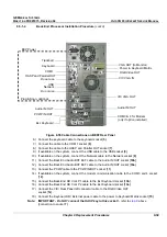
Figure 8-55 "Cable Connections on BEP2 Rear Panel" on
page 8-59
). Make sure that the HASP key (option plug) is connected to the correct connector
(parallel port).
NOTE:
For clarification, the numbers appearing in square brackets in the following steps correspond to the
numbers shown in the illustration of the BEP2 Rear Panel in
Figure 8-55 "Cable Connections on BEP2
Rear Panel" on page 8-59
.
2.) Connect the VIC VGA OUT (Left) cable to the VGA OUT socket [
1
]
on the BEP rear panel.
3.) Connect the VIC VGA IN (Right) cable to the VIC VGA IN socket [
2
].
4.) Connect the other end of this cable (i.e., the end labelled Back End) to the
VIC VGA OUT socket [
3
].
5.) Connect the trackball cable to the trackball socket [
4
].
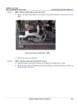
Figure 8-54 BEP - Position of Brackets on BEP2 Models
Lower Right
Bracket
Lower Left
Bracket
Upper
Bracket
Содержание Vivid 3N Pro Series
Страница 2: ......
Страница 5: ...GE MEDICAL SYSTEMS DIRECTION FK091075 REVISION 04 VIVID 3N PRO EXPERT SERVICE MANUAL ii iii...
Страница 24: ...GE MEDICAL SYSTEMS DIRECTION FK091075 REVISION 04 VIVID 3N PRO EXPERT SERVICE MANUAL xxii...
Страница 597: ......

