GE M
EDICAL
S
YSTEMS
D
IRECTION
FK091075, R
EVISION
04
V
IVID
3N P
RO
/E
XPERT
S
ERVICE
M
ANUAL
8-128
Section 8-8 - Peripherals
8-8-3-5
BIOS Setup
NOTE:
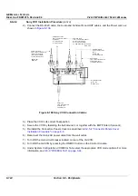
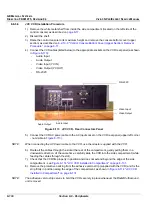
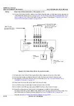
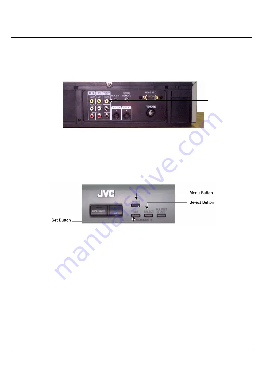
If you have an external monitor, you can connect it to the Monitor Out - Video socket on the VCR rear
panel (see
Figure 8-111
below), which will enable you to view the different menus as they are being
edited for the BIOS setup.
For best image quality during recording and playback, this is the
recommended setup procedure.
1.) Connect the AC power cable to the AC Input socket on the VCR rear panel (upper
left
corner) and
plug the other end of the cable into the mains power wall outlet.
2.) Turn ON power to the VCR.
3.) If an external monitor is connected to the VCR, make sure power to the monitor is also ON.
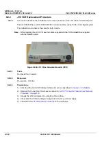
4.) Press the
Menu
button on the JVC Front Panel - see
Figure 8-112
below.
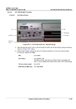
The LCD Display panel (refer to
Figure 8-110 "JVC VCR Front Panel - Switch Settings" on page 8-
127
) becomes illuminated.
NOTE:
If an external monitor is connected (see Note above), the Menu Switch Setting Screen is displayed (on
the external monitor). While making changes to the Menu Switch settings, these may be monitored in
this display.
If an external monitor is not connected, the Menu # and currently-selected value is only visible in the
LCD Display on the JVC VCR front panel.
Figure 8-111 JVC VCR - Rear Panel - External Monitor Connection
Figure 8-112 JVC VCR Front Panel Controls
Connect External
Monitor Here
(if available)
Содержание Vivid 3N Pro Series
Страница 2: ......
Страница 5: ...GE MEDICAL SYSTEMS DIRECTION FK091075 REVISION 04 VIVID 3N PRO EXPERT SERVICE MANUAL ii iii...
Страница 24: ...GE MEDICAL SYSTEMS DIRECTION FK091075 REVISION 04 VIVID 3N PRO EXPERT SERVICE MANUAL xxii...
Страница 597: ......


