GE M
EDICAL
S
YSTEMS
D
IRECTION
FK091075, R
EVISION
04
V
IVID
3N P
RO
/E
XPERT
S
ERVICE
M
ANUAL
Chapter 7 Diagnostics/Troubleshooting
7-41
7-3-8-5
TR Switch Test
If a solid line is observed during scanning, it may indicate a bad TR switch. This test checks the transmit
switches.
1) Connect a 3S probe and lock it in place.
NOTE:
To avoid irrelevant failure results, it is imperative that the probe be in good condition.
2) Access the
F.B.
tab of the
FE Diagnostics
dialog box, as described in
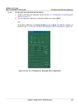
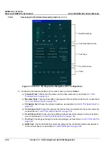
7-3-8-1 "Accessing the Front
Board Assembly Options" on page 7-27
.
3) In the
Select Socket
area of the
F.B.
tab, trackball to the socket to which the 3S probe is connected:
•
Trackball to
Left
,
Right
or
Center
and press
Select
.
4) Trackball to
Pulser 1
(High Voltage Power Supply [HVPS] +/-80V) or
Pulser 2
(Low Voltage Power
Supply [LVPS] +/-40V) and press
Select
.
5) Trackball to the
TR Switch Test
button and press
Select
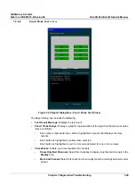
. The TR switch test is performed, and the
test results are displayed in the
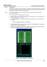
Report
dialog box, as shown below:
Figure 7-22 Report Dialog Box - TR Switch Test
Содержание Vivid 3N Pro Series
Страница 2: ......
Страница 5: ...GE MEDICAL SYSTEMS DIRECTION FK091075 REVISION 04 VIVID 3N PRO EXPERT SERVICE MANUAL ii iii...
Страница 24: ...GE MEDICAL SYSTEMS DIRECTION FK091075 REVISION 04 VIVID 3N PRO EXPERT SERVICE MANUAL xxii...
Страница 597: ......

