GE M
EDICAL
S
YSTEMS
D
IRECTION
FK091075, R
EVISION
04
V
IVID
3N P
RO
/E
XPERT
S
ERVICE
M
ANUAL
8-132
Section 8-8 - Peripherals
8-8-3-6 JVC VCR Installation Procedure
(cont’d)
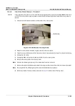
13.)Return the console bottom metal cover (upper section) (removed in
step 3
). Make sure the VCR
cable loom is properly aligned to pass through the slot in the cover and that there is no kinking or
pinching of the cables. Screw the cover firmly in position as described in
8-2-10-4 "Control Console
Bottom Cover (Upper Section) Installation Procedure" on page 8-19
.
14.)Re-install the Connectors Panel Cover as described in
8-2-5-4 "Connector Panels Cover
Installation Procedure" on page 8-8
.
15) Reconnect the mains AC power cable from the wall outlet.
16) Turn ON the main circuit breaker located on rear of the Vivid 3N.
17) Turn ON the Vivid 3N by pressing the ON/OFF button on the Control Console.
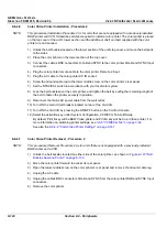
18.)Under System Configuration, VCR/ECG Tab, select the JVC VCR option. For more information, see
3-8-9 "VCR/ECG Tab" on page 3-44
.
19.)Insert a blank video casette tape into the VCR and perform a test recording to check correct
operation.
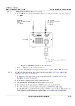
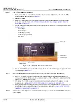
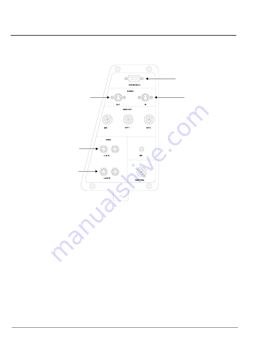
Figure 8-115 Vivid 3N Left Rear Panel Connectors
RS-232C
S-VIDEO IN
S-VIDEO OUT
AUDIO IN
AUDIO OUT
Содержание Vivid 3N Pro Series
Страница 2: ......
Страница 5: ...GE MEDICAL SYSTEMS DIRECTION FK091075 REVISION 04 VIVID 3N PRO EXPERT SERVICE MANUAL ii iii...
Страница 24: ...GE MEDICAL SYSTEMS DIRECTION FK091075 REVISION 04 VIVID 3N PRO EXPERT SERVICE MANUAL xxii...
Страница 597: ......

