GE M
EDICAL
S
YSTEMS
D
IRECTION
FK091075, R
EVISION
04
V
IVID
3N P
RO
/E
XPERT
S
ERVICE
M
ANUAL
7-30
Section 7-3 - Performing Front End (FE) Diagnostics
7-3-8-2 Transmit Test
(cont’d)
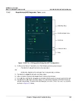
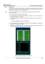
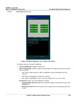
The
Report
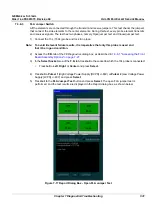
dialog box contains the following information:
•
Test Result Message:
Displays the test result.
•
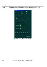
TR4 Modules:
Displays a graphic representation of the front board (four groups of TR4
sockets). Each group consists of four TR4 sockets, each socket containing four vectors
(channels), as follows:
•
Each vector is represented by a button (highlighted in green) that displays the number of
the socket to which the TR4 is connected.
•
Each button is highlighted yellow when selected.
•
Each button is highlighted red if errors were detected for one or more channels.
•
Checkboxes:
Enable you to manipulate bad channels:
•
Show Only Bad Channels:
Select this checkbox to display only bad channels in the
Display
area.
•
Mark bad channel:
Select this checkbox to manually mark the currently selected channel
as bad.
•
Vector Line:
Displays a graphic representation of the selected vector. This line is green if the
vector is good, and yellow if it is bad.
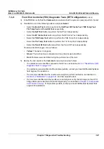
6) Check the test result message in the
Report
dialog box:
•
If one or more channels were identified as bad, trackball to the
Save Report
button and press
Select
, then contact a GE Medical Systems service representative.
•
If no channels were identified as bad, mark the channels suspected as being bad as follows:
•
Trackball to each of the channels in the
Display
area and press select.
•
Trackball to the
Mark bad channel
checkbox and press
Select
.
•
Trackball to
Save Report
and press
Select
, and contact a GE Medical Systems service
representative.
•
If no errors were identified, proceed with the next test.
•
If no errors were identified but the problem persists, contact your local GE Medical Systems
field engineer for assistance.
•
If errors were identified but the results were marginal, perform calibration, as described in
Section 6-8 "Calibration" on page 6-21
, and then repeat the test.
•
If errors were identified and the results were not marginal, verify that all image port and PCI
bridge cables are connected and functioning properly, as described in
Chapter 5 -
Components
and Function (Theory)
. If the problem persists, contact your local GE Medical Systems field
engineer for assistance.
7) Trackball to the
Exit
button and press
Select
. If required, repeat this test with a different pulser.
Содержание Vivid 3N Pro Series
Страница 2: ......
Страница 5: ...GE MEDICAL SYSTEMS DIRECTION FK091075 REVISION 04 VIVID 3N PRO EXPERT SERVICE MANUAL ii iii...
Страница 24: ...GE MEDICAL SYSTEMS DIRECTION FK091075 REVISION 04 VIVID 3N PRO EXPERT SERVICE MANUAL xxii...
Страница 597: ......


