GE M
EDICAL
S
YSTEMS
D
IRECTION
FK091075, R
EVISION
04
V
IVID
3N P
RO
/E
XPERT
S
ERVICE
M
ANUAL
8-68
Section 8-5 - Back End Parts Replacement
8-5-4
Plug & Scan Board Replacement Procedure
8-5-4-1
Tools
Use the appropriate flat and Phillips-type screw drivers and a wire cutter, as indicated in the Plug & Scan
board replacement procedure.
8-5-4-2
Preparation
Shut down the Vivid 3N Pro/Expert ultrasound unit, as described in
Chapter 3 -
Installation
. Voltage may
exist in the system when a Plug & Scan is present. Ensure that a full shutdown of the system is
performed, otherwise voltage might be present that can cause injury and/or damage.
8-5-4-3
Plug & Scan Board Removal Procedure
1) Remove the machine’s rear and left and right side covers, as described in
8-2-2-3 "Side Covers
Removal Procedure" on page 8-4
and
8-2-4-3 "Rear Cover Removal Procedure" on page 8-7
.
2) Disconnect the power cable from the rear of the BEP.
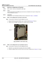
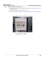
3) Remove the BEP side cover, as described in the appropriate procedure:
8-5-2-3 "BEP1 - Left and Right Side Cover Removal Procedure" on page 8-62
, or
8-5-3-3 "BEP2 -
Side Cover Removal Procedure" on page 8-64
.
4) If applicable, remove the octopus card holder as described in
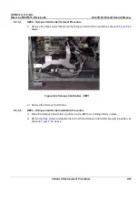
8-5-3-7 "BEP2 - Octopus Card Holder
Removal Procedure" on page 8-67
.
5) Disconnect all cables connected to the Plug & Scan board from the keyboard control card, the
battery and the power supply.
Note:
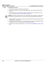
Counting from the top, the board is positioned in the first PCI slot.
6) Release the securing screw located on the left of the board bracket.
7) Gently remove the Plug & Scan board from the BEP.
8-5-4-4
Plug & Scan Board Installation Procedure
1) Gently insert the Plug & Scan board into its slot.
Note:
Counting from the top, the board is positioned in the first PCI slot.
2) Fasten the board with the screw on the left of the bracket.
3) Reconnect the cables to the Plug & Scan board from the keyboard control card, the battery and the
power supply.
4.) If applicable, mount the octopus card holder as described in
8-5-3-8 "BEP2 - Octopus Card Holder
Installation Procedure" on page 8-67
5) Mount the BEP side cover as described in the appropriate procedure:
8-5-2-4 "BEP1 - Left and Right Side Cover Installation Procedure" on page 8-62
, or
8-5-3-4 "BEP2
- Side Cover Installation Procedure" on page 8-64
.
6) Reconnect the power cable to the rear of the BEP.
7) Install the Vivid 3N rear, and left and right side covers, as described in
8-2-2-4 "Side Covers
Installation Procedure" on page 8-4
, and the
8-2-4-4 "Rear Cover Installation Procedure" on page
8-7
.
Note:
Perform a complete functional check of the Plug & Scan, as described in
- Functional
Checks.
Содержание Vivid 3N Pro Series
Страница 2: ......
Страница 5: ...GE MEDICAL SYSTEMS DIRECTION FK091075 REVISION 04 VIVID 3N PRO EXPERT SERVICE MANUAL ii iii...
Страница 24: ...GE MEDICAL SYSTEMS DIRECTION FK091075 REVISION 04 VIVID 3N PRO EXPERT SERVICE MANUAL xxii...
Страница 597: ......

