GE M
EDICAL
S
YSTEMS
D
IRECTION
FK091075, R
EVISION
04
V
IVID
3N P
RO
/E
XPERT
S
ERVICE
M
ANUAL
Chapter 3 Installation
3-13
3-5-3
Component Inspection
After verifying that all the required parts are included in the shipping crate, inspect the system
components using the checklist supplied below. In addition, ensure that all the labels described in
Section 1-4 "Product Labels and Icons" on page 1-9
are present, accurate and in good condition, and
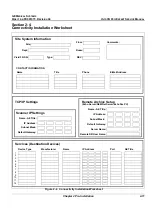
enter the serial number printed on the main label into the system installation details card, as described
in
3-11-1 "System Installation Details" on page 3-69
.
3-5-3-1
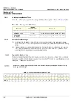
Damage Inspection Checklist
Visually inspect the contents of the shipping crate for damage. If any parts are damaged or missing,
contact an authorized GE Service Representative.
A
Damage Inspection Checklist
is provided in
Table 3-11 "Damage Inspection Checklist" on page 3-13
.
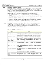
Table 3-11 Damage Inspection Checklist
Step
Item
Recommended Procedure
1
Console
Verify that the system is switched OFF and unplugged. Clean the console and
control panel.
2
Probe Holders
Clean the gel wells with warm water and a damp cloth to remove all traces of gel.
3
Control Panel
Physically inspect the control panel for missing or damaged items. Verify the proper
illumination of all the control panel buttons.
4
Probes
Check all probes for wear and tear on the lens, cable, and connector. Look for bent
or damaged pins on the connector and in the connector socket on the unit. Verify
that the EMI fingers around the probe connector socket housing are intact. Check
the probe locking mechanism and probe switch.
5
Monitor
Clean the CRT with a soft cloth dampened with water. Repeat using only water,
and wipe with a dry cloth. Inspect the monitor for scratches and raster burn.
6
Fans
Verify that the FE crate cooling fans, BE fan and peripheral fans are operating and
clean.
7
BE Rear Panel
Check the BE rear panel connectors for bent pins, loose connections and loose or
missing hardware. Screw all the cable connectors tightly to the connector sockets
on the panel. Verify that the labeling is in good condition.
8
Covers
Check that all screws are in place, all chassis and internal covers are installed and
that the air filters are in place.
9
Peripherals
Check and clean the peripherals in accordance with the manufacturer’s directions.
To prevent EMI or system overheating, dress the peripheral cables inside the
peripheral cover.
10
AC System
Check the AC board connectors and the associated cabling for good connection
and proper insulation. Verify that the connections are secured.
11
Power Cord
Check the power cord for cuts, loose hardware, tire marks, exposed insulation, or
any deterioration. Verify continuity. Tighten the clamps that secure the power cord
to the unit and the outlet plug to the cord. Replace the power cord and/or clamp, as
required.
12
Front Castors
Check that the front castors can swivel, and can be placed in swivel lock and full
lock by the foot brake pedal.
13
Rear Castors
Check that the rear castors can roll and swivel but cannot lock.
b
Содержание Vivid 3N Pro Series
Страница 2: ......
Страница 5: ...GE MEDICAL SYSTEMS DIRECTION FK091075 REVISION 04 VIVID 3N PRO EXPERT SERVICE MANUAL ii iii...
Страница 24: ...GE MEDICAL SYSTEMS DIRECTION FK091075 REVISION 04 VIVID 3N PRO EXPERT SERVICE MANUAL xxii...
Страница 597: ......

