GE M
EDICAL
S
YSTEMS
D
IRECTION
FK091075, R
EVISION
04
V
IVID
3N P
RO
/E
XPERT
S
ERVICE
M
ANUAL
Chapter 5 Components and Function (Theory)
5-37
5-5-16
PC-VIC Assembly
5-5-16-1
General Description
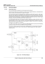
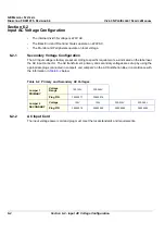
The PC-VIC assembly comprises the PC-VIC board and the I/O board.
The I/O board contains inputs and outputs; it receives all input signals, filters them, and transmits them
either to another external peripheral or to the PC-VIC board.
The PC-VIC board receives input signals from the VGA board and the PC2IP board. The VGA board
transmits SVGA signals which are filtered and transmitted to the Control Console Monitor. The SVGA
RGB signals are transmitted into the Video Input and Capturing circuit, where they are conditioned, and
only part of the transmitted image is captured and transmitted (in RGB format) to the S-Video C-Video
Converter circuit and to the RGB to Color Printer Converter circuit.
The PC2IP board controls the PC-VIC Power-on and also controls the operation of PC-VIC via an I
2
C
signal generated from the PCI bus of the BEP. The I
2
C signal determines the operation of the Video
Input and Capturing circuit and gives the command whether to operate in PAL or NTSC. It also defines
which region of the image is to be captured.
The RGB to Color Printer Converter circuit receives an RGB signal from the Video Input and Capturing
circuit and converts it to fit the level of RGB Color Printer standards.
The S-Video C-Video Converter circuit receives an RGB signal from the Video Input and Capturing
circuit and converts it into S-Video C-Video and sends a feedback signal to the Video Input and
Capturing circuit.
Figure 5-24 PC VIC Block Diagram
PC-VIC
Содержание Vivid 3N Pro Series
Страница 2: ......
Страница 5: ...GE MEDICAL SYSTEMS DIRECTION FK091075 REVISION 04 VIVID 3N PRO EXPERT SERVICE MANUAL ii iii...
Страница 24: ...GE MEDICAL SYSTEMS DIRECTION FK091075 REVISION 04 VIVID 3N PRO EXPERT SERVICE MANUAL xxii...
Страница 597: ......


