Maintenance and servicing
11.4 Replacing components
Drive converter cabinet units
Operating Instructions, 07/07, A5E00288214A
443
Preparatory steps
●
Disconnect the cabinet unit from the power supply.
●
Allow unimpeded access.
●
Remove the protective cover.
Removal
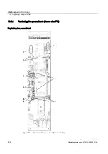
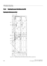
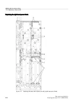
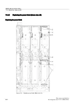
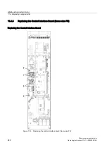
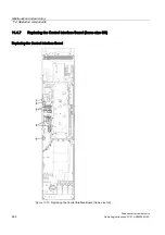
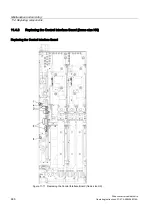
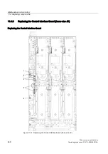
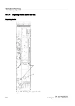
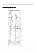
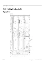
The steps for the removal procedure are numbered in accordance with the diagram.
1.
Remove the CU320 mounts (1 screw and 2 nuts). If necessary, remove the PROFIBUS
plug and connection to the operator panel (-X140 on the CU320) and remove the CU320.
2.
Disconnect the plugs for the fiber optic cables and signal cables (5 plugs).
3.
Remove the DRIVE-CLiQ cables and connections to the CU320 (5 plugs).
4.
Remove the retaining screws for the slide-in electronics unit (2 screws).
When removing the slide-in electronics unit, you have to disconnect 5 further plugs one
after the other (2 at the top, 3 at the bottom).
CAUTION
When removing the fan, ensure that you do not damage any signal cables.
The Control Interface Board can then be removed from the slide-in electronics unit.
CAUTION
When removing the connector of the ribbon cable, make sure that you actuate the locking
lever on the connector very carefully (e.g. with a screwdriver) otherwise the lock could be
damaged.
Installation
For re-installation, carry out the above steps in reverse order.
CAUTION
The tightening torques specified in the table "Tightening torques for connecting current-
carrying parts" must be observed.
Carefully re-establish the plug connections and ensure that they are secure.
When dealing with connectors with a lock, make sure that the locking lever is securely
engaged once connected.
The screwed connections for the protective covers must only be tightened by hand.

