
Electrical installation
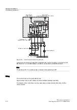
4.9 Other connections
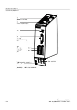
Drive converter cabinet units
112
Operating Instructions, 07/07, A5E00288214A
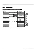
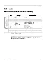
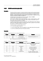
Terminal
Designation
Default value
Comments
17
18
Power Disconnection
EMERGENCY STOP circuit
30
31
Ready
Relay output (NO contact)
32
33
Motor turning
Relay output (NO contact)
34
DO (NO)
35
DO (COM)
36
DO (NC)
Fault
Relay output (two-way contact)
50/51
AI 0/4-20 mA
Speed setpoint
Default: 4 to 20 mA
60/61
AO 0/4-20 mA
Motor frequency
Default: 4 to 20 mA
62/63
AO 0/4-20 mA
Motor current
Default: 4 to 20 mA
Max. connectable cross-section: 2.5 mm² (AWG 12)
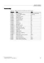
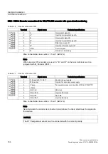
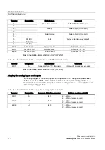
Table 4-51 Terminal block -A1-X3 – connection for the motor PTC thermistor sensor
Terminal
Designation
Default value
Comments
90/91
AI
Connection for a PTC thermistor
Shutdown if limit value is exceeded.
Max. connectable cross-section: 2.5 mm² (AWG 12)
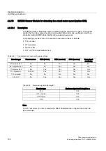
Adapting the analog inputs and outputs
If the setting ranges of the analog inputs and outputs are to be changed, the associated
interface converters (U401 / U402 / U403) must be set. The corresponding interface
converter must be removed for this purpose and the rotary switch on the side ("S1") turned
to the corresponding position.
Table 4-52 Terminal block -A1-X2 – Adaptation of analog inputs and outputs
Terminal
Designation
Item code of interface converter
Settings on rotary switch S1
50/51
AI
U401
2: 0 - 20 mA
4: 4 - 20 mA (preassignment)
60/61
AO
U402
1: 0 - 20 mA
2: 4 - 20 mA (preassignment)
62/63
AO
U403
1: 0 - 20 mA
2: 4 - 20 mA (preassignment)