


Electrical installation
4.8 Signal connections
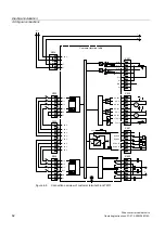
Drive converter cabinet units
64
Operating Instructions, 07/07, A5E00288214A
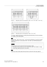
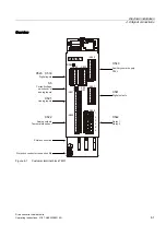
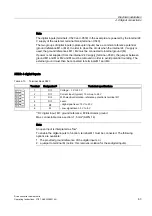
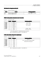
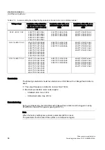
X530: 4 digital inputs
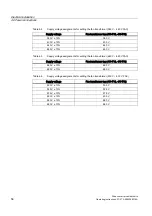
Table 4-11 Terminal block X530
Terminal
Designation
1)
Technical specifications
1
DI 4
2
DI 5
3
DI 6
4
DI 7
5
M2
6
M
Voltage: - 3 V to 30 V
Current input (typical): 10 mA up to 24 V
With electrical isolation: The reference potential is terminal M2
Level:
- High signal level: 15 V to 30 V
- Low signal level: -3 V to 5 V
1)
DI: digital input; M2: ground reference; M: Electronics ground
Max. connectable cross-section: 1.5 mm² (AWG 14)
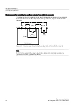
Note
An open input is interpreted as "low".
To enable the digital inputs to work, terminal M2 must be connected. The following options
are available:
1.
The provided ground reference of the digital inputs, or
2.
a jumper to terminal M (notice: this removes isolation for these digital inputs).
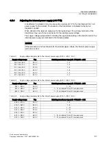
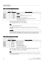
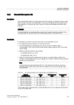
X521: 2 analog inputs (differential inputs)
Table 4-12 Terminal block X521
Terminal
Designation
1)
Technical specifications
1
AI 0+
2
AI 0-
3
AI 1+
4
AI 1-
-10 V - +10 V, Ri = 70 kΩ
+4 mA - +20 mA
-20 mA - +20 mA, Ri = 250 Ω
0 mA - +20 mA (factory setting)
5
P10
+10 V ± 1 %, Imax 5 mA
6
M
Reference potential for AI 0
7
N10
-10 V ± 1 %, Imax 5 mA
8
M
Reference potential for AI 1
1)
AI: analog input; P10/N10: auxiliary voltage, M: Ground reference
Max. connectable cross-section: 1,5 mm² (AWG 14)
CAUTION
The input current of the analog inputs must not exceed 35 mA when current measurements
are performed.


