Electrical installation
4.9 Other connections
Drive converter cabinet units
Operating Instructions, 07/07, A5E00288214A
77
4.9.8
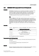
EMERGENCY STOP category 0; 230 V AC or 24 V DC (option L57)
Description
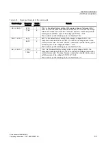
EMERGENCY STOP category 0 for uncontrolled stop to EN 60204. This function involves
disconnecting the cabinet unit from the supply via the line contactor bypassing the
electronics by means of a safety combination to EN 60204-1. The motor then coasts to a
stop. To prevent the main contactor from switching under load, an OFF2 is triggered
simultaneously. The operational status is indicated by means of three LEDs (-A120).
In the factory setting, this version is set with a 230 V AC button circuit.
Note
When the EMERGENCY STOP button is pressed, the motor coasts to an uncontrolled
standstill and the main motor voltage is disconnected (to EN 60204-1 (VDE 0113)). Auxiliary
voltages (e.g. for separately-driven fans or anti-condensation heating) may still be present.
Certain sections of the converter (e.g., the closed-loop controller or any auxiliary equipment)
may also remain live. If all the voltages have to be completely disconnected, the
EMERGENCY STOP button must be integrated in a protection concept, which must be
implemented on the system side. For this purpose, an NC contact is installed at terminal -
X120.
Connection
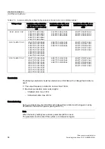
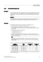
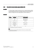
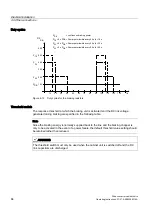
Table 4-26 Terminal block X120 – connection for EMERGENCY STOP category 0, 230 V AC and 24
V DC
Terminal
230 V AC and 24 V DC button circuit
7
8
Loop in EMERGENCY STOP button from line side,
remove jumpers 7-8.
15
16
"On" for monitored start:
Remove bridges 15–16 and connect button.
17
18
Checkback "trip safety combination"
Max. connectable cross-section: 4 mm
2
(AWG 10)
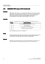
Reconnection to the 24 V DC Button Circuit
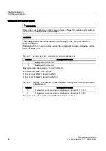
When using the 24 V DC button circuit, you must remove the following jumpers at terminal
block X120:
●
4-5, 9-10, and 11-14
You must also insert the following jumpers at terminal block X120:
●
4-11, 5-10, and 9-14
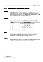
Diagnosis
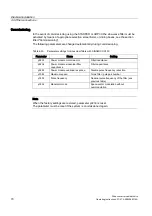
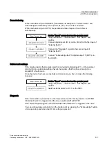
Messages output during operation and in the event of faults (meaning of LEDs at -A120) are
described in "Additional operating instructions" in the operating instructions.

