


Setpoint channel and closed-loop control
7.3 V/f control
Drive converter cabinet units
266
Operating Instructions, 07/07, A5E00288214A
7.3
V/f control
Description
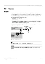
The simplest solution for a control procedure is the V/f characteristic, whereby the stator
voltage for the induction motor or synchronous motor is controlled proportionately to the
stator frequency. This method has proved successful in a wide range of applications with low
dynamic requirements, such as:
●
Pumps and fans
●
Belt drives
●
Multi-motor drives
V/f control aims to maintain a constant flux (Φ) in the motor, whereby the flux is proportional
to the magnetization current (Iµ) or the ratio of voltage (U) to frequency (f).
Φ ~ Iµ ~ V/f
The torque (M) generated by the induction motors is, in turn, proportional to the product (or,
more precisely, the vector product (Φ x I)) of the flux and current.
M ~ Φ x I
To generate as much torque as possible with a given current, the motor must function using
the greatest possible constant flux. To maintain a constant flux (Φ), therefore, the voltage (V)
must change in proportion to the frequency (f) to ensure a constant magnetization current
(Iµ). V/f characteristic control is derived from these basic premises.
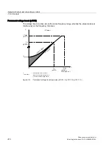
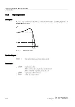
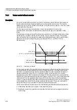
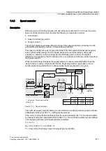
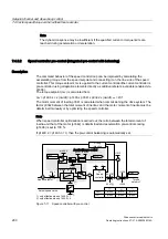
The field-weakening range is above the rated motor frequency, where the maximum voltage
is reached. The flux and maximum torque decrease as the frequency increases; this is
illustrated in the following diagram.
I
803˓
0
Q
˓
Q
I
Q
I
PD[
0˓
83
83
0RWRUQRPLQDO
ZRUNLQJSRLQW
)LHOGUDQJH
9ROWDJHUDQJH
Figure 7-4
Operating areas and characteristic curves for the induction motor with converter supply
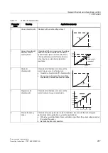
Several variations of the V/f characteristic exist, which are listed in the following table.