Electrical installation
4.9 Other connections
Drive converter cabinet units
Operating Instructions, 07/07, A5E00288214A
111
4.9.22
NAMUR terminal block (option B00)
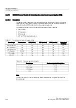
Description
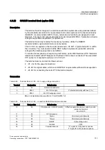
The terminal block is designed in accordance with the requirements and guidelines defined
by the standards association for measurement and control systems in the chemical industry
(NAMUR – recommendation NE37), that is, certain device functions are assigned to fixed
terminals. The inputs and outputs assigned to the terminals fulfill PELV ("protective extra-low
voltage and protective separation") requirements.
The terminal block only contains the necessary functions. Unlike the NAMUR
recommendation, optional terminals are not available.
The 24 V DC is supplied on the line side via terminals –A1-X2:1-3 (protected with 1 A within
the converter). You must ensure that the PELV safety requirements (protective extra-low
voltage with protective separation) are fulfilled.
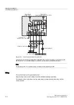
To monitor the temperature of explosion-proof motors, option B00 features a PTC thermistor
release mechanism with PTB approval. Shutdown if limit value is exceeded. The associated
PTC sensor is connected to terminal –A1-X3:90, 91.
The terminal block is divided into three sections:
●
-X1; -X2: for the power connections
●
-A1-X2: for signal cables, which must fulfill PELV requirements with electrical separation.
●
-A1-X3: for connecting the motor PTC thermistor detector
Connection
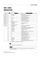
Table 4-49 Terminal block -A1-X2 – 24 V supply voltage connection
Terminal
Designation
Default value
Comments
1
M
Reference conductor
2
P24 V
24 V DC supply
Protected internally with fuse (1 A)
3
P24 V
24 V DC outgoing circuit
Max. connectable cross-section: 2.5 mm² (AWG 12)
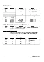
Table 4-50 Terminal block -A1-X2 – connection NAMUR control terminal block
Terminal
Designation
Default value
Comments
10
DI
ON (dynamic) / ON/OFF (static)
Effective operation can be coded by a wire
jumper on terminal
–A1-400:9;10.
11
DI
OFF (dynamic)
12
DI
Faster
Motorized potentiometer
13
DI
Slower
Motorized potentiometer
14
DI
RESET
Acknowledge error
15
DI
Interlock
OFF2
16
DI
Counterclockwise
"0" signal for CW phase sequence
"1" signal for CCW phase sequence

