


Technical specifications
12.3 Technical specifications
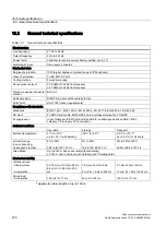
Drive converter cabinet units
Operating Instructions, 07/07, A5E00288214A
485
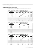
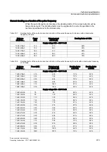
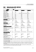
Table 12-11 Version A, 380 V – 480 V 3 AC, part 3
Category
Unit
Order No. 6SL3710-
7LE37-5AA0
7LE38-4AA0
7LE41-0AA0
Rated motor output
at 400 V, 50 Hz
at 460 V, 60 Hz
kW
hp
400
600
450
700
560
800
Rated input voltage
V
380 V to 480 V 3 AC ± 10% (-15% < 1 min)
Rated input current
1)
A
674
759
888
Rated output current
A
745
840
985
Base-load current I
L2)
A
725
820
960
Base-load current I
H3)
A
570
700
860
Max. output frequency
4)
Hz
100
100
100
Power loss
kW
18.0
18.4
24.4
Cooling air requirement
m³/s
1.96
1.96
2.6
Sound pressure level at 50/60 Hz dB(A)
77/79
77/79
77/79
Line connection
Recommended: DIN VDE
5)
Maximum: DIN VDE
AWG/MCM
Fixing screw
mm
2
mm
2
2 x 300
4 x 240
4 x (500)
M12 (2 holes)
4 x 150
8 x 240
8 x (500)
M12 (4 holes)
4 x 185
8 x 240
8 x (500)
M12 (4 holes)
Motor connection
Recommended: DIN VDE
5)
Maximum: DIN VDE
AWG/MCM
Fixing screw
mm
2
mm
2
2 x 300
4 x 240
4 x (500)
M12 (2 holes)
4 x 150
4 x 240
4 x (500)
M12 (2 holes)
4 x 185
6 x 240
6 x (500)
M12 (3 holes)
Protective conductor connection
Fixing screw
M12 (10 holes)
M12 (16 holes)
M12 (18 holes)
Approx. weight (standard version) kg
1731
1778
2408
Frame sizes
Active Interface Module
Active Line Module
Motor Module
HI
HX
HX
HI
HX
HX
JI
JX
JX
Dimensions (standard version)
Width x height x depth
mm
2200 x 2,000 x 600
2200 x 2,000 x 600
2800 x 2,000 x 600
Recommended protection
Line protection
(with option L26)
Rated current
Frame size to DIN 43620-1
Line and semi-cond. protection
(without option L26)
Rated current
Frame size to DIN 43620-1
A
A
3NA3475
800
4
3NE1448-2
850
3
Circuit breaker
Circuit breaker
Circuit breaker
Circuit breaker
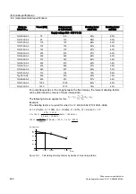
1)
The currents are based on a power factor of cos ϕ = 1 and include 10 A for the external auxiliary equipment (as used, for
example, with options L19 or B03).
2)
The base-load current (I
L
) is based on a duty cycle of 110% for 60 s or 150% for 10 s with a duty cycle duration of 300 s
(see "Overload capability").
3)
The base-load current (I
H
) is based on a duty cycle of 150% for 60 s or 160% for 10 s with a duty cycle duration of 300 s
(see "Overload capability").
4)
Maximum output frequency at factory-set default pulse frequency (for information on increasing the output frequency,
see "Functions, monitoring and protective functions/Increasing the output frequency"; for information on derating data, see
"Derating data").
5)
The recommendations for the North American market in AWG or MCM must be taken from the appropriate NEC
(National Electrical Code) or CEC (Canadian Electrical Code) standards.