Functions, monitoring, and protective functions
9.4 Extended functions
Drive converter cabinet units
340
Operating Instructions, 07/07, A5E00288214A
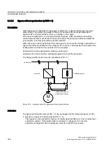
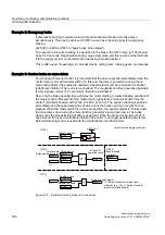
Example: liquid level control
The objective here is to maintain a constant level in the container.
This is carried out by means of a variable-speed pump in conjunction with a sensor for
measuring the level.
The level is determined via an analog input (e.g. AI0 TM31) and sent to the technology
controller. The level setpoint is defined in a fixed setpoint. The resulting controlled variable is
used as the setpoint for the speed controller.
In this example, a Terminal Module (TM31) is used.
6HQVRU
DFW
;
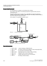
Figure 9-7
Level control: Application
;
;
7HFBFWUW\SH
7HFBFWU.S 7HFBFWU7Q
7HFBFWU
6HWSRLQW
$FWXDOYDOXH
5DPSIXQFWLRQJHQHUDWRU
6HWS
$FWXDO
QBVHWS
S
G
GW
S
S
S
S S
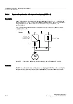
Figure 9-8
Level control: Controller structure
Key control parameters
•
p1155 = r2294
n_setp1 downstream of RFG [FD 3080]
•
p2253 = r2224
Technology controller setpoint effective via fixed setpoint [FD 7950]
•
p2263 = 1
D component in fault signal [FD 7958]
•
p2264 = r4055
Actual value signal X
actual
via AI0 of TM31 [FP 9566]
•
p2280 = Kp
Calculate P gain by means of optimization
•
p2285 = Tn
Calculate integral time by means of optimization
•
p2200 = 1
Technology controller enabled

