Operation
6.6 PROFIBUS
Drive converter cabinet units
Operating Instructions, 07/07, A5E00288214A
207
6.6.5
Description of control words and setpoints
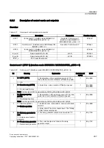
Overview
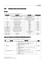
Table 6-11 Overview of control words and setpoints
Abbreviation
Description
Parameters
Function diagram
STW 1
Control word 1 (interface mode SINAMICS /
MICROMASTER, p2038 = 0)
See table "Control word 1
(interface mode SINAMICS /
MICROMASTER, p2038 = 0)"
FP2442
STW 1
Control word 1 (interface mode PROFIdrive VIK-
NAMUR, p2038 = 2)
See table: "Control word 1"
FP2441
STW 2
Control word 2 (interface mode SINAMICS /
MICROMASTER, p2038 = 0)
FP2444
N_set_A
Speed setpoint A (16-bit)
p1070
FP3030
N_set_B
Speed setpoint B (32-bit)
p1155
FP3080
PCS7_x
PCS7-specific setpoints
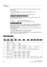
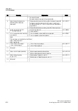
Control word 1 (STW 1) (interface mode SINAMICS / MICROMASTER, p2038 = 0)
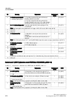
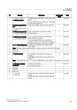
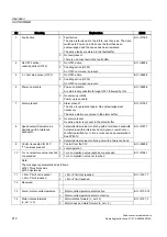
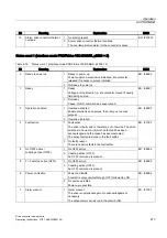
Table 6-12 Control word 1 (interface mode SINAMICS / MICROMASTER, p2038 = 0)
Bit
Meaning
Explanation
Betriebsbedi
ngung
BICO
0 = OFF1 (OFF1)
0: Deceleration on the deceleration ramp (p1121),
then pulse block, main contactor (if fitted) is opened.
0
1 = ON
1
BI: p0840
0 = Coast to stop (OFF2)
0: Pulse block, main contactor (if fitted) is opened
1
BI: p0844
BI: p0845
1 = Do not coast to stop
1
Note: Control signal OFF2 is generated by ANDing BI: p0844 and BI: p0845
0 = Emergency stop
(OFF3)
0: Deceleration on the rapid-stop ramp (p1135), then
pulse block, main contactor (if fitted) is opened.
1 = No emergency stop
1
BI: p0848
2
Note: Control signal OFF3 is generated by ANDing BI: p0848 and BI: p0849.
1: Enable inverter, pulse enable, ramp-up with active
setpoint
3
0 = Disable operation
1 = Enable operation
0: Pulse inhibit. The motor coasts down. The "Ready
To Run" status remains set.
1
BI: p0852
0: The ramp generator output is set to setpoint "0".
4
0 = Set ramp generator to
zero
1 = Enable ramp-function
generator
1
BI: p1140
0: The current setpoint is frozen at the ramp
generator output.
5
0 = Freeze ramp generator
1 = Restart ramp generator
1
BI: p1141

