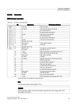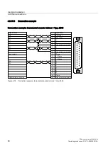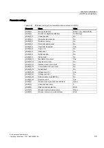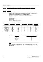
Electrical installation
4.9 Other connections
Drive converter cabinet units
90
Operating Instructions, 07/07, A5E00288214A
Diagnosis
Messages output during operation and in the event of faults (meaning of LEDs on –A101)
are described in "Additional Operating Instructions" in the operating manual.
4.9.15
Communication Board Ethernet CBE20 (option G33)
Description
Interface module CBE20 is used for communication via PROFINET.
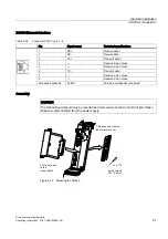
The module is delivered mounted in a supplementary pack on the CU320 Control Unit and
must be installed line-side in the option slot of the CU320 Control Unit.
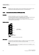
4 Ethernet interfaces are available on the module. Diagnosis of the function mode and
communication are possible via LEDs.
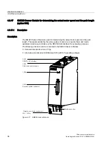
Interface overview
3RUW
;LQWHUIDFHV
(WKHUQHWLQWHUIDFHV
3RUW
3RUW
3RUW
/('V
6\QFJUHHQ
)DXOWUHG
Figure 4-13 Communication Board Ethernet CBE20
MAC address
The MAC address of the Ethernet interfaces is indicated on the upper side of the CBE20.
The label is only visible when the module has not yet been installed.
Note
Please note the MAC address prior to installing the module so that it is available to you for
the subsequent commissioning.

