


Operation
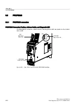
6.6 PROFIBUS
Drive converter cabinet units
Operating Instructions, 07/07, A5E00288214A
203
6.6.2
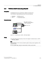
Control via Profibus
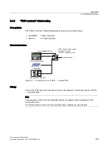
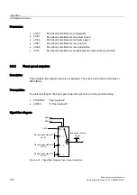
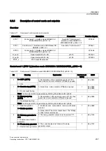
"DP1 (PROFIBUS)" diagnostics LED
The PROFIBUS diagnostics LED is located on the front of the Control Unit CU320. Its
statuses are described in the following table.
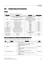
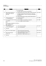
Table 6-8
Description of the LEDs
Color
State
Description
-----
OFF
Cyclic communication has not (yet) taken place.
Green
Steady light
PROFIBUS is ready for communication and cyclic communication is taking place.
Green
0.5 Hz flashing
light
Full cyclic communication is not yet taking place.
Possible causes: The master is not transmitting setpoints.
Red
Steady light
Cyclic communication has been interrupted.
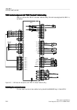
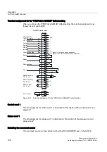
Setting the PROFIBUS Address
Two methods are available for setting the PROFIBUS address:
●
The address switches (DIP switches) on the front of the Control Unit behind the cover
plate (see "PROFIBUS connection"). In this case, p0918 is read-only and shows the
address setting.
A change to the switch only becomes effective after the Control Unit has been switched
on.
●
Entering parameter p0918 via the operator panel.
You can only do this if the address has been set to 0 or 127, that is, all switches from S1
to S7 are set to ON or OFF.
In this case, changes become effective immediately.
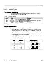
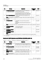
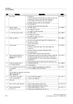
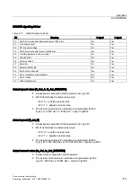
Table 6-9
PROFIBUS address switches
Switch
Significance
Technical specifications
S1
2
0
= 1
S2
2
1
= 2
S3
2
2
= 4
S4
2
3
= 8
S5
2
4
= 16
S6
2
5
= 32
S7
2
6
= 64
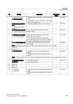
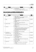
6LJQLILFDQFH
([DPSOH
21
2))
6
21
2))
6