


Functions, monitoring, and protective functions
9.3 Drive functions
Drive converter cabinet units
328
Operating Instructions, 07/07, A5E00288214A
9.3.8
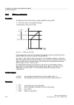
Increasing the output frequency
In applications that require higher output frequencies, the pulse frequency of the converter
may have to be increased.
It may also be necessary to change the pulse frequency to prevent resonance from
occurring.
Since increasing the pulse frequency also increases the switching losses, a derating factor
for the output current must be taken into account when the drive is configured.
Once the pulse frequency has been increased, the new output currents are automatically
included in the calculation for power unit protection.
Note
Use of a sine-wave filter (option L15) must be selected using p0230 = 3 when
commissioning. This setting fixes the pulse frequency to 4 kHz or 2.5 kHz and it cannot be
changed.
The following maximum output frequencies can be achieved with the default pulse
frequencies listed below.
Table 9-4
Maximum output frequency with default pulse frequency
Converter rating
[kW]
Default pulse frequency
[kHz]
Maximum output frequency
[Hz]
Supply voltage 380 – 480 V 3 AC
110 – 250
2
160
315 – 800
1,25
100
Supply voltage 660 – 690 V 3 AC
75 – 1200
1,25
100
Supply voltage 500 – 690 V 3 AC
75 – 1200
1,25
100
The pulse frequencies set in the factory are also the minimum frequencies.
The scanning times for the inputs and outputs of the customer terminal block TM31 are set in
the factory to 4000 µs. This is also the minimum limit.