


Electrical installation
4.9 Other connections
Drive converter cabinet units
86
Operating Instructions, 07/07, A5E00288214A
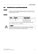
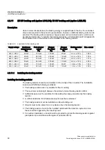
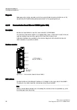
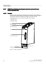
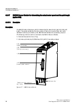
4.9.12
Thermistor motor protection unit (option L83/L84)
Description
This option includes the thermistor motor protection unit (with PTB approval) for PTC
thermistor sensors (PTC resistor type A) for warning and shutdown. The power supply for
the thermistor motor protection unit is provided inside the converter where the evaluation is
also performed.
Option L83 triggers the "external alarm 1" (A7850) if a fault occurs.
Option L84 triggers the "external fault 1" (F7860) if a fault occurs.
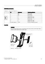
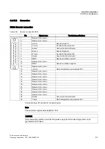
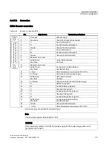
Connection
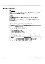
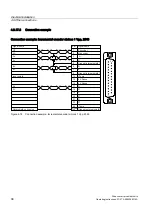
Table 4-34 F127/F125 – connection for thermistor motor protection unit
Equipment designation
Description of Functions
-F127:T1,T2
Thermistor motor protection (alarm)
-F125: T1, T2
Thermistor motor protection (shutdown)
The PTC thermistor sensors are connected directly to terminals T1 and T2 of the evaluation
unit.
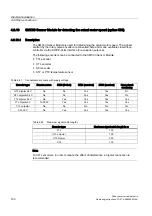
Table 4-35 Maximum cable length for the sensor circuit
Line cross-section in mm²
Line length in m
2.5
2 x 2800
1.5
2 x 1500
0.5
2 x 500
Diagnosis
Messages output during operation and in the event of faults (meaning of LEDs on -F125, -
F127) are described in "Additional Operating Instructions" in the operating manual.