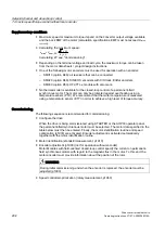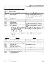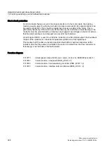
Setpoint channel and closed-loop control
7.4 Vector speed/torque control with/without encoder
Drive converter cabinet units
Operating Instructions, 07/07, A5E00288214A
283
7.4.3.3
Reference model
Description
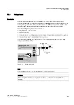
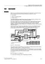
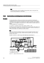
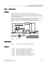
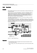
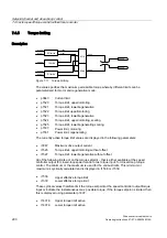
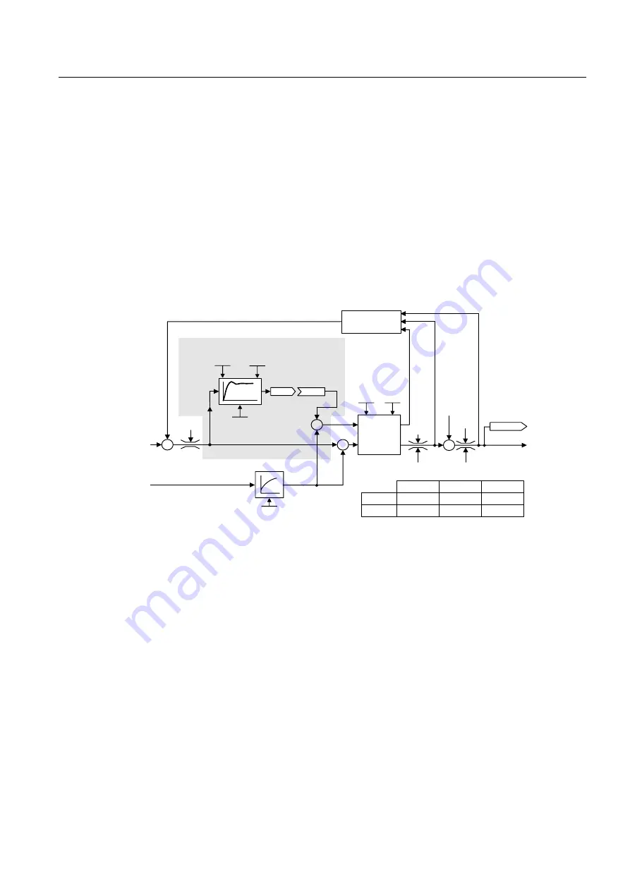
The reference model becomes operative when p1400.3 = 1 and p1400.2 = 0.
The reference model is used to emulate the speed control loop with a P speed controller.
The loop emulation can be set in p1433 to p1435. It becomes effective if p1437 is connected
to the output of the model r1436.
The reference model delays the setpoint-actual value deviation for the integral component of
the speed controller so that settling (stabilizing) operations can be suppressed.
The reference model can also be externally emulated and the external signal entered via
p1437.
-
-
r 1547 [ 0 ]
r 1538
r 1547 [ 1 ] r
1539
SLVC :
VC :
p 1452
p 1442
p 1470
p 1460
p 1472
p 1462
K
p
T
n
K
p
T
n
r 1084
r 0079
T
i
T
i
p 1437
r 1436
r 1515
-
p 1433 p
1435
I
P
p 1434
$FWXDOVSHHGYDOXH
6SHHGVHWSRLQW
5HIHUHQFHPRGHOSUHFRQWURO
5HIHUHQFHPRGHOSUHFRQWURO
3,
6SHHG
FRQWUROOHU
7RUTXH
VHWSRLQW
'URRS
LQMHFWLRQ
Figure 7-12 Reference model
Function diagram
FP 6031
Pre-control balancing reference/acceleration model
Parameters
•
p1400.3 Reference model speed setpoint I component
•
p1433
Speed controller reference model natural frequency
•
p1434
Speed controller reference model damping
•
p1435
Speed controller reference model dead time
•
r1436
Speed controller reference model speed setpoint output
•
p1437
Speed controller reference model I component input

