Operation
6.3 Basic information about the drive system
Drive converter cabinet units
Operating Instructions, 07/07, A5E00288214A
177
6.3.3
Data sets
Description
For many applications, it is beneficial if more than one parameter can be changed
simultaneously by means of one external signal during operation/when the system is ready
for operation.
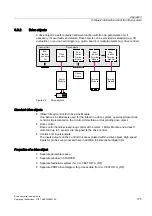
This can be carried out using indexed parameters, whereby the parameters are grouped
together in a data set according to their functionality and indexed. Indexing allows several
different settings, which can be activated by switching the data set, to be defined in each
parameter.
Note
The command and drive data sets can be copied in STARTER (Drive -> Configuration ->
"Command data sets" or "Drive data sets" tab).
The displayed command and drive data sets can be selected in the associated STARTER
screen forms..
CDS: Command data set
The BICO parameters (binector and connector inputs) are grouped together in a command
data set. These parameters are used to interconnect the signal sources of a drive (see
"Operation/BICO technology: Interconnecting signals").
By parameterizing several command data sets and switching between them, the drive can
be operated with different pre-configured signal sources.
A command data set contains the following (examples):
●
Binector inputs for control commands (digital signals)
–
ON/OFF, enable signals (p0844, etc.)
–
Jog (p1055, etc.)
●
Connector inputs for setpoints (analog signals)
–
Voltage setpoint for V/f control (p1330)
–
Torque limits and scaling factors (p1522, p1523, p1528, p1529)
Two command data sets are available.
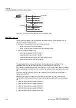
The following parameters are available for selecting command data sets and for displaying
the currently selected command data set:
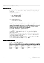
Table 6-1
Command data set: selection and display
Display
CDS
Select bit 0
p0810
selected (r0836)
active (r0050)
0
0
0
0
1
1
1
1
If a command data set, which does not exist, is selected, the current data set remains active.

