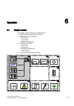


Operation
6.3 Basic information about the drive system
Drive converter cabinet units
182
Operating Instructions, 07/07, A5E00288214A
Parameters
•
p0120
Power Module data sets (PDS) number
•
p0130
Motor data sets (MDS) number
•
p0139[0...2]
Copy motor data set (MDS)
•
p0140
Encoder data sets (EDS) number
•
p0170
Command data set (CDS) number
•
p0180
Drive data set (DDS) number
•
p0186
Assigned motor data set (MDS)
•
p0187[0...n]
Encoder 1 encoder data set number
•
p0188[0...n]
Encoder 2 encoder data set number
•
p0189[0...n]
Encoder 3 encoder data set number
•
p0809
Copy command data set CDS
•
p0810
BI: Command data set selection CDS bit 0
•
p0811
BI: Command data set selection CDS bit 1
•
p0812
BI: Command data set selection CDS bit 2
•
p0813
BI: Command data set selection CDS bit 3
•
p0819[0...2]
Copy drive data set DDS
•
p0820
BI: Drive data set selection, bit 0
•
p0821
BI: Drive data set selection, bit 1
•
p0822
BI: Drive data set selection, bit 2
•
p0823
BI: Drive data set selection, bit 3
•
p0824
BI: Drive data set selection, bit 4
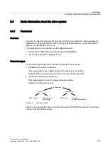
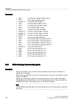
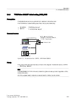
6.3.4
BICO technology: Interconnecting signals
Description
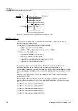
Every drive contains a large number of interconnectable input and output variables and
internal control variables.
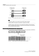
BICO technology ( Binector Connector Technology) allows the drive to be adapted to a wide
variety of conditions.
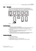
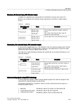
Digital and analog signals, which can be connected freely by means of BICO parameters,
are identified by the prefix BI, BO, CI or CO in their parameter name. These parameters are
identified accordingly in the parameter list or in the function diagrams.
Note
The STARTER parameterization and commissioning tool is recommended when using BICO
technology.