

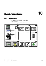


Diagnosis / faults and alarms
10.2 Diagnosis
Drive converter cabinet units
414
Operating Instructions, 07/07, A5E00288214A
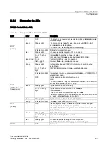
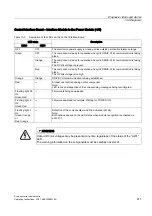
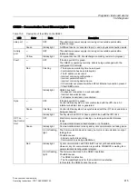
SMC20 – encoder evaluation (-A82)
Table 10-7 Description of the LEDs on the SMC20
LEDs
Color
Status
Description
---
OFF
The electronics power supply is missing or lies outside the
permissible tolerance range.
Green
Continuous
The component is ready for operation and cyclic DRIVE-CLiQ
communication is taking place.
Orange
Continuous
DRIVE-CLiQ communication is being established.
Red
Continuous
At least one fault is pending on this component.
Note:
LED is driven irrespective of the corresponding messages being
reconfigured.
0.5 Hz flashing light Firmware is being downloaded.
Green/red
2 Hz flashing light
Firmware download is complete. Wait for POWER ON.
RDY
Green/orange
or
red/orange
2 Hz flashing light
Detection of the components via LED is activated (p0144).
Note:
Both options depend on the LED status when module recognition is
activated via p0144 = 1.
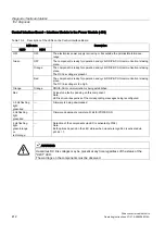
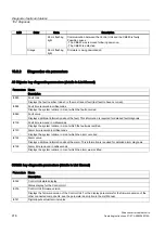
SMC30 – encoder evaluation (-A81)
Table 10-8 Description of the LEDs on the SMC30
LED
Color
State
Description
---
OFF
The electronics power supply is missing or lies outside permissible
tolerance range.
Green
Steady light
The component is ready for operation and cyclic DRIVE-CLiQ
communication is taking place.
Orange
Steady light
DRIVE-CLiQ communication is being established.
Red
Steady light
At least one fault is pending on this component.
Note:
LED is driven irrespective of the corresponding messages being
reconfigured.
0.5 Hz flashing light Firmware is being downloaded.
Green / red
2 Hz flashing light
Firmware download is complete. Waiting for POWER ON.
RDY
Green Orange
or
Red Orange
2 Hz flashing light
Detection of the components via LED is activated (p0144).
Note: Both options depend on the LED status when module
recognition is activated via p0144 = 1.
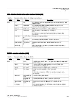
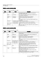
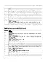
---
OFF
Electronic power supply missing or outside permissible tolerance
range.
Measuring system supply ≤ 5 V (only when ready for operation).
OUT>5 V
Orange
Steady light
Electronic power supply for measuring system present.
Measuring system supply > 5 V.
Notice: You must ensure that the connected encoder can be
operated with a 24 V supply.
Operating an encoder designed for a 5 V supply with a 24 V supply
can damage the encoder electronics beyond repair.