

Output terminals
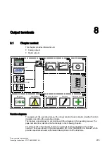
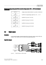
8.3 Digital outputs
Drive converter cabinet units
Operating Instructions, 07/07, A5E00288214A
299
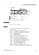
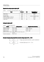
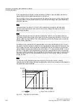
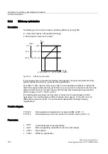
Example: changing analog output 0 from current to voltage output –10 V ... +10 V and setting the
characteristic
Voltage output present at terminal 1, ground is at terminal 2
Set TM31.AO_type [analog output 0] to -10 V ... +10 V.
Set TM31.AO_char. x1 to 0.00 %.
Set TM31.AO_char. y1 to 0.000 V.
Set TM31.AO_char. x2 to 100.00%.
Set TM31.AO_char. y2 to 10.000 V.
8.3
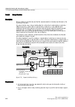
Digital outputs
Description
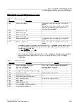
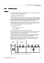
Four bi-directional digital outputs (terminal X541) and two relay outputs (terminal X542) are
available. These outputs are, for the most part, freely parameterizable.
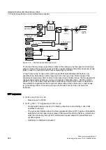
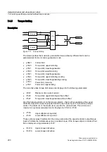
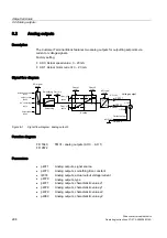
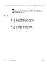
Signal flow diagram
,QYHUVLRQ
5HDG\WRVWDUW
2SHUDWLRQHQDEOHG
5DPSXSUDPSGRZQ
FRPSOHWHG
5HDG\WRRSHUDWH
U
U
U
U
S
S
S
S
S
S
'2
'2
;
','2
','2
','2
','2
;
0
S
S
S
Figure 8-2
Signal flow diagram: Digital outputs