


Electrical installation
4.9 Other connections
Drive converter cabinet units
104
Operating Instructions, 07/07, A5E00288214A
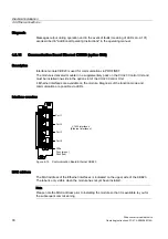
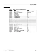
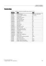
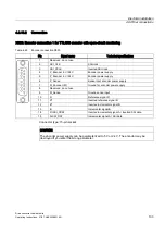
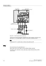
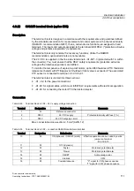
X521 / X531: Encoder connection 2 for HTL/TTL/SSI encoder with open-circuit monitoring
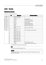
Table 4-46 Encoder connection X521
Terminal
Signal name
Technical specifications
1
A
Incremental signal A
2
A*
Inverted incremental signal A
3
B
Incremental signal B
4
B*
Inverted incremental signal B
5
R
Reference signal R
6
R*
Inverted reference signal R
7
CTRL
Control signal
8
M
Ground via inductivity
Max. connectable cross-section: 1.5 mm² (AWG 14)
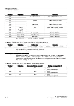
Note
When unipolar HTL encoders are used, A*, B*, and R* on the terminal block must be
jumpered with M_Encoder (X531).
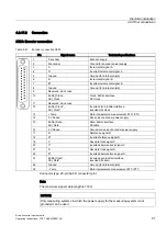
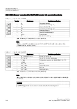
Table 4-47 Encoder connection X531
Terminal
Signal name
Technical specifications
1
P_Encoder 5 V / 24 V
Encoder power supply
2
M_Encoder
Ground for encoder power supply
3
-Temp
4
+Temp
Temperature sensor connection KTY84-1C130/PTC
5
SSI_CLK
SSI clock
6
SSI_XCLK
Inverted SSI clock
7
SSI_DAT
SSI data
8
SSI_XDAT
Inverted SSI data
Max. connectable cross-section: 1.5 mm² (AWG 14)
Note
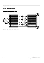
Note that when the encoder is connected via terminals, the cable shield must be applied to
the module.
NOTICE
The KTY temperature sensor must be connected with the correct polarity.