

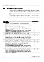
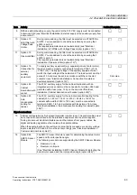
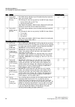
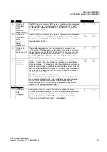


Electrical installation
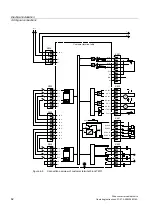
4.5 EMC-compliant design
Drive converter cabinet units
50
Operating Instructions, 07/07, A5E00288214A
4.5
EMC-compliant design
The following section provides some basic information and guidelines that will help you
comply with the EMC and CE guidelines.
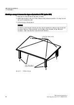
cabinet assembly
●
Connect painted or anodized metal components using toothed self-locking screws or
remove the insulating layer.
●
Use unpainted, de-oiled mounting plates.
●
Establish a central connection between ground and the protective conductor system
(ground).
Shield gaps
●
Bridge shield gaps (at terminals, circuit-breakers, contactors, and so on) with minimum
impedance and the greatest possible surface area.
Using large cross-sections
●
Use underground and grounding cables with large cross-sections or, better still, with litz
wires or flexible cables.
Laying the motor supply cable separately
●
The distance between the motor supply cable and signal cable should be > 20 cm. Do not
lay power cables and motor supply cables in parallel to each other.
Securing the potential to ground between modules with widely differing interference potential
●
Lay an equalizing cable parallel to the control cable (the cable cross-section must be at
least 16 mm²).
●
If relays, contactors, and inductive or capacitive loads are connected, the switching relays
or contactors must be provided with anti-interference elements.
Cable installation
●
Cables that are subject to or sensitive to interference should be laid as far apart from
each other as possible.
●
Noise immunity increases when the cables are laid close to the ground potential. For this
reason, you are advised to lay these cables in corners and at ground potential.
●
Ground the spare cables on at least one end.
●
Long cables should be shortened or laid in noise resistant areas to avoid additional
connecting points.