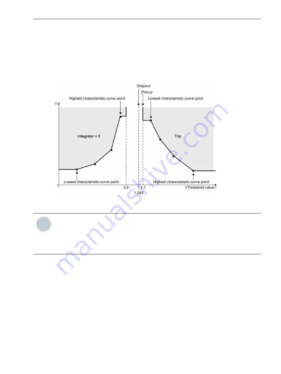
An integrating method of measurement totalizes the weighted time. The weighted time results from the char-
acteristic curve. For this, the time that is associated with the present current value is determined from the
characteristic curve. Once the weighted time exceeds the value 1, the stage operates.
When the measured value falls short of the pickup value by a factor of 1.045 (0.95 x 1.1 x threshold value),
the dropout is started. The pickup will be indicated as clearing. You can influence the dropout behavior via
setting parameters. You can select between instantaneous dropout (totalized time is deleted) or dropout
according to the characteristic curve (reduction of totalized time depending on the characteristic curve). The
dropout according to characteristic curve (disk emulation) is the same as turning back a rotor disk. The
weighted reduction of the time is initiated from 0.9 of the set threshold value.
[dwocpken-140611-02.tif, 2, en_US]
Figure 6-102
Pickup Behavior and Dropout Behavior when Using a User-Defined Characteristic Curve
i
i
NOTE
Note that the currents that are lower than the current value of the smallest characteristic-curve point do
not extend the operate time. The pickup characteristic runs in parallel to the current axis up to the smallest
characteristic-curve point. Currents that are larger than the current value of the largest characteristic-curve
point do not reduce the operate time. The pickup characteristic runs in parallel to the current axis from the
largest characteristic-curve point.
Application and Setting Notes
This stage is structured the same way as the stage with the inverse-time characteristic curve. The only differ-
ence is that you can define the characteristic curve as desired. This chapter only provides application and
setting notes for setting characteristic curves.
Parameter:
Current/time value pairs
(from the operate curve)
Use these settings to define the characteristic curve. Set a current/time value pair for each characteristic-curve
point. The setting depends on the characteristic curve you want to realize.
Set the current value as a multiple of the threshold value. Siemens recommends that you set the
Threshold
parameter to
1.00
in order to obtain a simple relation. You can change the threshold value setting afterwards
if you want to displace the characteristic curve.
Set the time value in seconds. The characteristic curve is displaced using the
Time dial
parameter.
6.12.5.2
Protection and Automation Functions
6.12 Overcurrent Protection, 1-Phase
SIPROTEC 5, Overcurrent Protection, Manual
531
C53000-G5040-C017-8, Edition 07.2017
Summary of Contents for 7SJ82
Page 8: ...8 SIPROTEC 5 Overcurrent Protection Manual C53000 G5040 C017 8 Edition 07 2017 ...
Page 38: ...38 SIPROTEC 5 Overcurrent Protection Manual C53000 G5040 C017 8 Edition 07 2017 ...
Page 60: ...60 SIPROTEC 5 Overcurrent Protection Manual C53000 G5040 C017 8 Edition 07 2017 ...
Page 186: ...186 SIPROTEC 5 Overcurrent Protection Manual C53000 G5040 C017 8 Edition 07 2017 ...
Page 194: ...194 SIPROTEC 5 Overcurrent Protection Manual C53000 G5040 C017 8 Edition 07 2017 ...
Page 966: ...966 SIPROTEC 5 Overcurrent Protection Manual C53000 G5040 C017 8 Edition 07 2017 ...
Page 1072: ...1072 SIPROTEC 5 Overcurrent Protection Manual C53000 G5040 C017 8 Edition 07 2017 ...
Page 1236: ...1236 SIPROTEC 5 Overcurrent Protection Manual C53000 G5040 C017 8 Edition 07 2017 ...
Page 1306: ...1306 SIPROTEC 5 Overcurrent Protection Manual C53000 G5040 C017 8 Edition 07 2017 ...
Page 1370: ...1370 SIPROTEC 5 Overcurrent Protection Manual C53000 G5040 C017 8 Edition 07 2017 ...
Page 1404: ...1404 SIPROTEC 5 Overcurrent Protection Manual C53000 G5040 C017 8 Edition 07 2017 ...
Page 1576: ...1576 SIPROTEC 5 Overcurrent Protection Manual C53000 G5040 C017 8 Edition 07 2017 ...
Page 1614: ...1614 SIPROTEC 5 Overcurrent Protection Manual C53000 G5040 C017 8 Edition 07 2017 ...
Page 1634: ...1634 SIPROTEC 5 Overcurrent Protection Manual C53000 G5040 C017 8 Edition 07 2017 ...


