


Influence of Other Functions via Dynamic Settings
The influence of these functions via dynamic settings is described in chapter
6.3.8.2 Application and Setting Notes (Advanced Stage)
.
Application Notes for Parallel Lines and Cable Runs with Infeed at Both Ends
Parallel Lines or Transformers
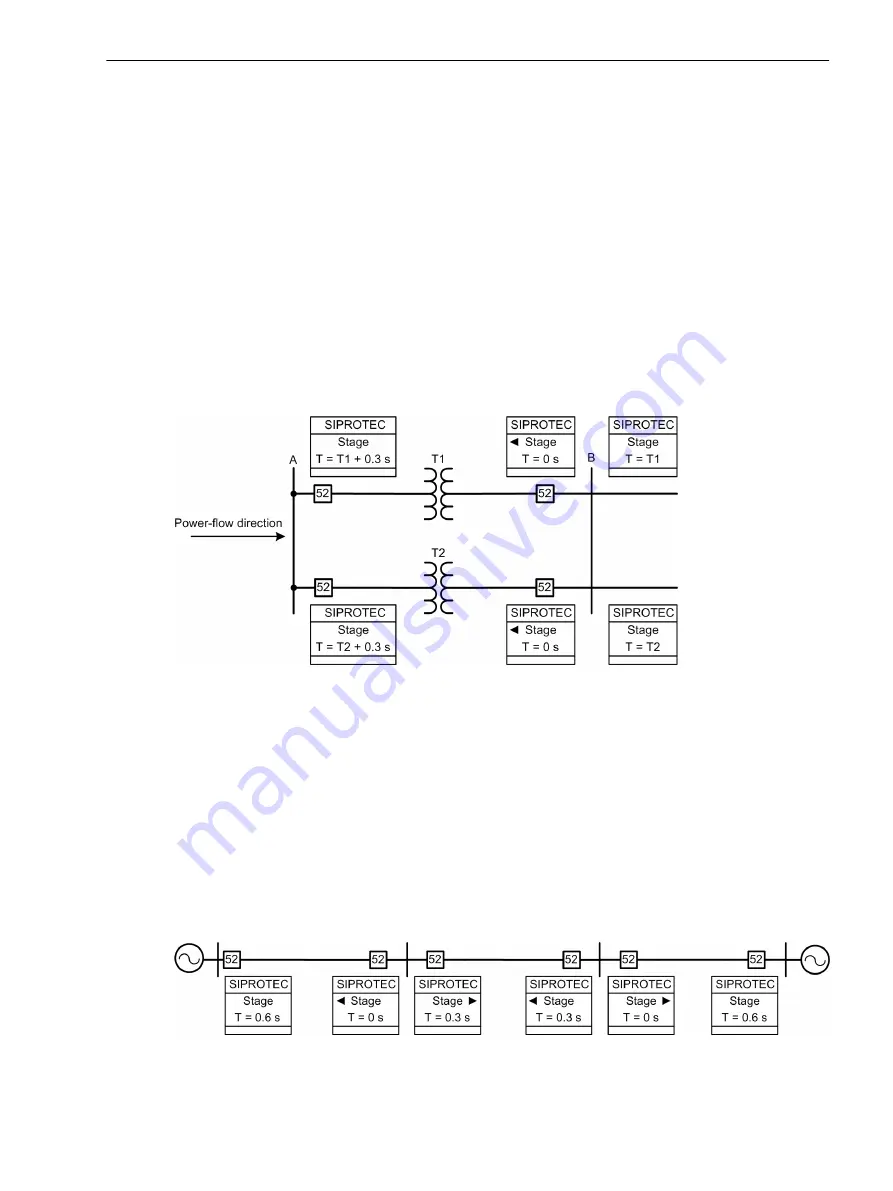
In parallel lines or transformers with infeed at one end (see
), if there is no directional measuring
element, a fault on feeder T1 will also trip the other feeder T2. In contrast, a directional measuring element in
the devices on busbar B prevents the tripping of the circuit breaker in the parallel feeder. Therefore, in
, directional overcurrent protection is used in the places marked with direction arrows. Please note
that the forward direction of the protection device represents the direction towards the object to be protected.
This does not have to be the same as the power direction of normal power flow.
Set time grading in opposition to the power flow with increasing time. As load can only flow in one direction,
you can set the directional devices without time delay.
[dwdocp05-240611-01.tif, 1, en_US]
Figure 6-58
Parallel Line with Transformers
Legend for
Stage ▶:
Stage:
T:
Directional stage, forward direction set
Non-directional stage
Grading time
Cable Runs with Infeed at Both Ends
Cable runs with infeed at both ends and lines connected to form ring topologies also require that you supple-
ment overcurrent protection with the directional criterion.
shows a ring system implementation,
with the 2 infeeds shown merging in the ring to form a single infeed. For the directional devices whose
forward direction matches the power-flow direction, set time grading in opposition to the power flow with
increasing time. As power flow from both ends is possible, grading has to be set at both ends.
[dwdocp06-240611-01.tif, 1, en_US]
Figure 6-59
Cable Runs with Infeed at Both Ends
6.6.8
6.6.9
Protection and Automation Functions
6.6 Directional Overcurrent Protection, Phases
SIPROTEC 5, Overcurrent Protection, Manual
437
C53000-G5040-C017-8, Edition 07.2017
Summary of Contents for 7SJ82
Page 8: ...8 SIPROTEC 5 Overcurrent Protection Manual C53000 G5040 C017 8 Edition 07 2017 ...
Page 38: ...38 SIPROTEC 5 Overcurrent Protection Manual C53000 G5040 C017 8 Edition 07 2017 ...
Page 60: ...60 SIPROTEC 5 Overcurrent Protection Manual C53000 G5040 C017 8 Edition 07 2017 ...
Page 186: ...186 SIPROTEC 5 Overcurrent Protection Manual C53000 G5040 C017 8 Edition 07 2017 ...
Page 194: ...194 SIPROTEC 5 Overcurrent Protection Manual C53000 G5040 C017 8 Edition 07 2017 ...
Page 966: ...966 SIPROTEC 5 Overcurrent Protection Manual C53000 G5040 C017 8 Edition 07 2017 ...
Page 1072: ...1072 SIPROTEC 5 Overcurrent Protection Manual C53000 G5040 C017 8 Edition 07 2017 ...
Page 1236: ...1236 SIPROTEC 5 Overcurrent Protection Manual C53000 G5040 C017 8 Edition 07 2017 ...
Page 1306: ...1306 SIPROTEC 5 Overcurrent Protection Manual C53000 G5040 C017 8 Edition 07 2017 ...
Page 1370: ...1370 SIPROTEC 5 Overcurrent Protection Manual C53000 G5040 C017 8 Edition 07 2017 ...
Page 1404: ...1404 SIPROTEC 5 Overcurrent Protection Manual C53000 G5040 C017 8 Edition 07 2017 ...
Page 1576: ...1576 SIPROTEC 5 Overcurrent Protection Manual C53000 G5040 C017 8 Edition 07 2017 ...
Page 1614: ...1614 SIPROTEC 5 Overcurrent Protection Manual C53000 G5040 C017 8 Edition 07 2017 ...
Page 1634: ...1634 SIPROTEC 5 Overcurrent Protection Manual C53000 G5040 C017 8 Edition 07 2017 ...


