


You can select the control direction using the following values at the Val input of the BSC_DEF block.
•
1 means step up
•
0 means step down
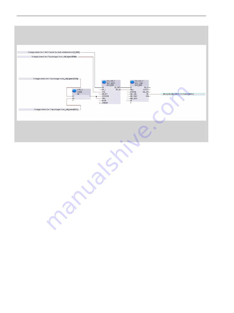
[scbivctv-280715-01, 3, en_US]
Figure 8-90
CFC Chart
Using this simple CFC chart, pressing the function keys to step up or down incrementally can be displayed.
Motor Supervision Time
The runtime of the motor drive can be monitored from the device. This function is used to identify failures of
the motor drive during switching and to trip actions if necessary. To use the
Motor supervision time
,
you must route the motor sliding contact (most significant binary input) and set the proper motor runtime.
The motor sliding contact is active until the tap changer has reached the new position. This time is compared
to the
Motor supervision time
. If the new tap position is not reached within the motor runtime, the
Motor sup. time expired
indication is set. The
Trigger motor prot. sw.
indication with which
the motor can be switched off is output for a duration of 1.5 s.
Adjusting-Command Monitoring
Adjusting-ommand monitoring is used for checking the proper operation of the tap-changer mechanism. The
Tap changer function calculates the next logical tap position as a result of the higher/lower command. The
time of position detection is determined as a function of the availability of the motor sliding contact. After
resetting the active motor sliding contact, the Tap changer function reads the new tap position value. If the
value for the calculated tap position could not be received within the parameterized time
Motor supervi-
sion time
, the error message
Position failure
is issued.
The following position errors of the tap changer are considered during this:
•
Invalid tap position: The tap position is outside the predefined range of
minimum value
and
maximum
value
•
Adjusting command in the wrong direction (for example, if a higher tap was commanded and the tap
changer responds with a lower position and vice versa)
•
No operation of the tap changer (for example, if the tap-changer motor is defective or the position indi-
cation is not functioning)
•
Illogical tap-change operation (for example, if no logical tap position following the previous position is
indicated)
Control Functions
8.8 Transformer Tap Changers
1184
SIPROTEC 5, Overcurrent Protection, Manual
C53000-G5040-C017-8, Edition 07.2017
Summary of Contents for 7SJ82
Page 8: ...8 SIPROTEC 5 Overcurrent Protection Manual C53000 G5040 C017 8 Edition 07 2017 ...
Page 38: ...38 SIPROTEC 5 Overcurrent Protection Manual C53000 G5040 C017 8 Edition 07 2017 ...
Page 60: ...60 SIPROTEC 5 Overcurrent Protection Manual C53000 G5040 C017 8 Edition 07 2017 ...
Page 186: ...186 SIPROTEC 5 Overcurrent Protection Manual C53000 G5040 C017 8 Edition 07 2017 ...
Page 194: ...194 SIPROTEC 5 Overcurrent Protection Manual C53000 G5040 C017 8 Edition 07 2017 ...
Page 966: ...966 SIPROTEC 5 Overcurrent Protection Manual C53000 G5040 C017 8 Edition 07 2017 ...
Page 1072: ...1072 SIPROTEC 5 Overcurrent Protection Manual C53000 G5040 C017 8 Edition 07 2017 ...
Page 1236: ...1236 SIPROTEC 5 Overcurrent Protection Manual C53000 G5040 C017 8 Edition 07 2017 ...
Page 1306: ...1306 SIPROTEC 5 Overcurrent Protection Manual C53000 G5040 C017 8 Edition 07 2017 ...
Page 1370: ...1370 SIPROTEC 5 Overcurrent Protection Manual C53000 G5040 C017 8 Edition 07 2017 ...
Page 1404: ...1404 SIPROTEC 5 Overcurrent Protection Manual C53000 G5040 C017 8 Edition 07 2017 ...
Page 1576: ...1576 SIPROTEC 5 Overcurrent Protection Manual C53000 G5040 C017 8 Edition 07 2017 ...
Page 1614: ...1614 SIPROTEC 5 Overcurrent Protection Manual C53000 G5040 C017 8 Edition 07 2017 ...
Page 1634: ...1634 SIPROTEC 5 Overcurrent Protection Manual C53000 G5040 C017 8 Edition 07 2017 ...


