3.1 Generation of Measurement Conditions
3 - 22
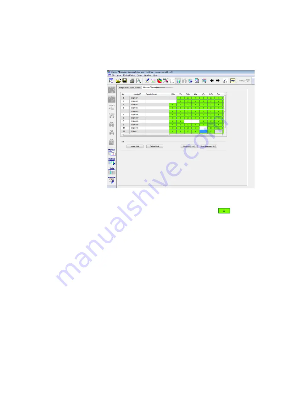
(7) Setting of Measurement Object
Click the [Measure Object] tab (<1> in Fig. 3-19) to display
the Measure Object window.
Fig. 3-19 Measure Object Window
The sample to be measured is indicated by
, and
specification can be made per element. For selecting the
measurement object, click the relevant row, and when it
turns blue, click the row again or click the [Measure (UNK)]
button. To deselect a measurement object, similarly, click
the relevant row, and when it turns blue, click the row again
or click the [Not Measure (UNK)] button.
A [QC] button (<8> in Fig. 3-1) is provided on the Method
window and checks on RSD, working curve and other items can
be made.
But quantitative measurements can be carried out even if these
functions are not utilized.
Described here as a simple measurement example is a normal
quantitative measurement where QC conditions are not entered.
In this case, the procedure is advanced without making any
settings on the QC window.
<1>
3.1.8 Setting
QC
Conditions
Summary of Contents for ZA3000 Series
Page 423: ...9 3 5 9 11 Fig 9 14 Diagnosis Log Dialog Box ...
Page 449: ...10 5 Reflecting on Analysis Conditions 10 24 Fig 10 16 Method Window Unmark the checkbox ...
Page 455: ...INDEX 4 V Verify 3 34 W Working curve graph 4 1 Wavelength accuracy 9 1 ...
Page 456: ...INSTRUCTION MANUAL 7J1 9027 000 Ver 1 February 2016 MODEL HFS 4 HYDRIDE FORMATION SYSTEM ...


