3.1 Generation of Measurement Conditions
3 - 2
When the Method window is not yet opened, click the [Method]
button (<13> in Fig. 3-1) on the toolbox and the Method window
will appear.
Click the [Measurement Mode] button (<1> in Fig. 3-1) to open
the measurement mode window.
(1) Click
the
▼
button (<11> in Fig. 3-1) at the right end of the
Measurement Mode item and then click [Flame] from the
list that appears. (No other modes can be selected for
ZA3300). The measurement conditions that will be
displayed upon changing the measurement mode will be
the latest ones set previously for that mode.
(2) Click
the
▼
button (<12> in Fig. 3-1) at the right end of the
Sample Introduction item and then select [Manual] from the
list that appears.
(3) For [Operator], [Analysis Name] and [Comment], desired
characters can be input after clicking each input box.
However, analysis can be carried out with no inputs in
these fields. Also, [Operator], [Analysis Name] and
[Comment] can be corrected in [Parameter List] on the
Data Process window after measurement.
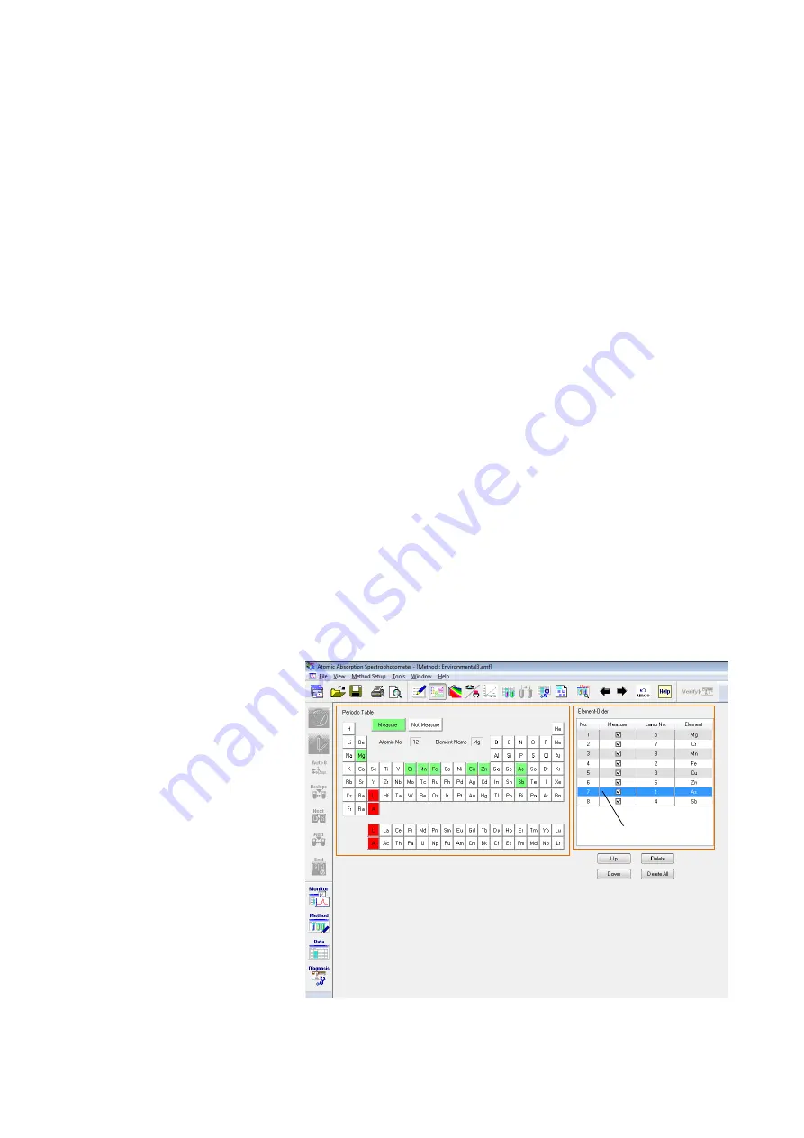
(1) Click the [Elements] button (<2> in Fig. 3-1) to display the
Elements window.
Fig. 3-2 Elements Window
3.1.1 Displaying
the
Method Window
3.1.2 Setting
Measurement
Mode
3.1.3 Setting
Analyte
Element
<1>
<2>
<3>
Summary of Contents for ZA3000 Series
Page 423: ...9 3 5 9 11 Fig 9 14 Diagnosis Log Dialog Box ...
Page 449: ...10 5 Reflecting on Analysis Conditions 10 24 Fig 10 16 Method Window Unmark the checkbox ...
Page 455: ...INDEX 4 V Verify 3 34 W Working curve graph 4 1 Wavelength accuracy 9 1 ...
Page 456: ...INSTRUCTION MANUAL 7J1 9027 000 Ver 1 February 2016 MODEL HFS 4 HYDRIDE FORMATION SYSTEM ...


