


26
EN
O R I G I N A L I N S T R U C T I O N S
activate the VRD function, press and hold the multifunction knob for approximately 5 seconds. If symbol ‘h’ on the display is on, the
function is activated. In the MMA welding mode, by turning the multifunction knob, set the welding current appropriate to the type
and thickness of the materials to be welded in the range of 40 A - 180 A. The welding current setting will be displayed graphically
(c), and the unit (f) and the welding current value in the
fi
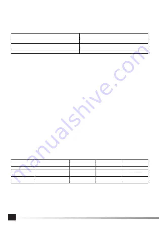
eld (j) will also be displayed. Typical welding current values depending
on the electrode diameter are shown below.
Electrode diameter [mm]:
Welding current [A]
1.6
20 – 50
2
40 – 60
2.5
60 – 80
3.2
80 – 140
4
120 – 200
Cover your face with a welding shield and start the welding operation. For easier arc initiation, move the electrode towards the
point from which welding will be started. Once the electrode has made contact with the material to be welded, lift and tilt the elec-
trode slightly to maintain a constant length arc.
After
fi
nishing the work, ensure that the earth clamp and the electrode remaining in the torch are isolated from each other. They
do not come into contact and the electrode or its clamp does not come into contact with the welded material. Switch o
ff
the welder
by turning the switch to the o
ff
position (O). If you can still hear the fan running and the power light is still on, this means that the
welder is cooling the electronics, and after that it will automatically switch o
ff
the fan and the power light. Do not unplug the power
cord from the mains socket during that time. This could lead to the welder electronics overheating. Welding cables can be discon-
nected. After the fan has been automatically switched o
ff
, unplug the power cable of the welder and then set about maintenance.
Lift TIG welding
CAUTION! Before starting work, read the tips described in the section of the manual “Tips on how to use the lift TIG welding
method”.
Assemble the non-consumable electrode torch according to the recommendations of the torch manufacturer. Put the plug of
the cable into the socket and then turn it clockwise as far as possible. Ensure that the plug cannot not slide out of the socket by
itself. Connect the current connector of the TIG torch to the “-” terminal, and the earthing cable plug to the “+” terminal. Place the
non-consumable electrode in the body of the TIG torch. Connect the spring clamp to the metal part of the element to be welded.
The contact area should be cleared of oil, paint or other contaminants that may impair the
fl
ow of current. Connect the gas hose
directly to the regulator located on the gas cylinder by using a quick-release coupling or a hose clamp. Set the desired shielding
gas pressure using the cylinder regulator and by reading the value on the manometer.
Ensure that the earth clamp and the
electrode are isolated from each other and do not come into contact, and that the electrode or its clamp does not come
into contact with the material to be welded.
Plug the power cord plug into the mains socket. Turn the switch on the back of the
unit to the “on” position (I). The welder fan will automatically switch on if the unit needs to be cooled down. The welder display (II)
will show the value of the welding current in the
fi
eld (j) and the operating mode (a) (b). Brie
fl
y pressing the multifunction knob
toggles the welder parameters, and turning the knob adjusts the value of the selected parameter. Before welding, set the welding
mode by brie
fl
y pressing the multifunction knob. When a symbol (b) appears on the display, this means that the LIFT TIG welding
mode has been selected; then, by turning the multifunction knob, set the welding current appropriate to the type and thickness of
the materials to be welded in the range of 10 A - 180 A. The welding current setting will be displayed graphically (c), and the unit
(f) and the welding current value in the
fi
eld (j) will also be displayed. Below are typical values the welding current and gas
fl
ow
depending on the electrode diameter and the thickness of the material welded in the case of welding stainless steel.
Thickness of material [mm]
Tungsten electrode diameter [mm]
Filler diameter [mm]
Welding current [A]
Gas
fl
ow [l/min]
0.5
1.0
1.0
35 – 40
4 – 6
0.8
1.0
1.0
35 – 45
4 – 6
1.0
1.6
1.6
40 – 70
5 – 8
1.5
1.6
1.6
50 – 85
6 – 8
2.0
2.0 – 2.5
2.0
80 – 130
8 – 10
3.0
2.5 – 3.0
2.25
120 – 150
10 – 12
Cover your face with a welding shield and start the welding operation. Open the shielding gas valve. After approx. 2 seconds,
strike the arc by bringing the tungsten electrode into contact with the workpiece and then lifting it to a distance of approx. 2 - 3
mm to engage the arc. Guide the torch with continuous motion along the entire weld, keeping a constant length of the arc. To
fi
nish welding, lift the torch to interrupt the arc. Close the gas valve. After
fi
nishing the work, ensure that the earth clamp and the
electrode remaining in the torch are isolated from each other. They do not come into contact and the electrode or its clamp does
not come into contact with the welded material. Switch o
ff
the welder by turning the switch to the o
ff
position (O). If the fan is still
audible, this means that the welder is cooling the electronics, and after that it will automatically switch o
ff
the fan and the welder
Содержание YT-81355
Страница 43: ...43 RU 230 50 30...
Страница 44: ...44 RU O 16 EN 60204 1 TIG lift YT 81357 YT 81358...
Страница 45: ...45 RU TIG lift TIG TIG 2 1 1 5 II 70 80 III 5 IV TIG lift YT 81357 YT 81358 TIG 2 3 70 80 VI 6 30 VII...
Страница 54: ...54 UA 230 50 30...
Страница 55: ...55 UA 16 EN 60204 1 TIG lift YT 81357 YT 81358 TIG lift TIG...
Страница 56: ...56 UA TIG 2 1 1 5 II 70 80 III 5 IV TIG lift YT 81357 YT 81358 TIG 2 3 70 80 VI 6 30 VII 10 10...
Страница 57: ...57 UA YT 81355 HOT START ARC FORCE ANTI STICK VRD O C O C MMA I 30 140 1 6 20 50 2 40 60 2 5 60 80 3 2 80 140 O...
Страница 62: ...62 UA a 10 50 DC PULSE 2 3 O EN 60974 10 IEC 61000 3 12 0 3 toya24 pl...
Страница 168: ...168 GR 1 2 3 4 5 6 TIG 7 8 9 10 11 11 11 40 C 12 12 12 13 13 13 14 50 Hz 60 Hz 15 16 17 22 24 CE 230 V 50 Hz 30 mA...
Страница 169: ...169 GR...
Страница 170: ...170 GR O 16 A EN 60204 1 MMA TIG lift YT 81357 YT 81358 TIG lift TIG TIG...
Страница 177: ...177 GR 10 50 a DC PULSE 2 3 mm O EN 60974 10 RTV IEC 61000 3 12 0 3 MPa toya24 pl...
Страница 179: ...179 BG 1 2 3 4 5 6 TIG 7 8 9 10 11 11a 11b 40 12 12a 12b 13 13a 13b 14 50 Hz 60 Hz 15 16 17 22 24 230 V 50 Hz 30 mA...
Страница 180: ...180 BG...
Страница 181: ...181 BG O 16 A EN 60204 1 MMA TIG lift YT 81357 YT 81358 TIG lift TIG TIG...
Страница 188: ...188 BG h e a 10 50 DC PULSE j e 10 50 a DC PULSE 2 3 mm O EN 60974 10 IEC 61000 3 12 0 3 MPa toya24 pl...
Страница 211: ...211 AR TIG CE...
Страница 212: ...212 AR O EN MMA YT YT TIG lift TIG TIG lift...
Страница 213: ...213 AR TIG MMA II III IV YT YT TIG lift TIG VII VI YT HOT START ARC FORCE ANTI STICK VRD O C O C MMA MMA...
Страница 217: ...217 AR MENU DC PULSE DC PULSE DC PULSE h a e h DC PULSE e j DC PULSE O EN A IEC toya pl...
Страница 218: ...I N S T R U K C J A O R Y G I N A L N A 218...