11
12
13
14
15
16
17
18
19
20
411
15. (A) Application Parameters
15.9 Offline auto tuning for a frequency search
• Offline auto tuning is not performed correctly when the surge voltage suppression filter (FR-ASF-H/FR-BMF-H) is inserted
between the inverter and motor. Be sure to remove them before performing tuning.
Setting
1.
Set "11" in
Pr.96 Auto tuning setting/status
.
2.
Set the rated motor current (initial value is inverted rated current) in
Pr.9 Electronic thermal O/L relay
. (Refer to
3.
Set
Pr.71 Applied motor
according to the motor to be used.
Performing tuning
• Before performing tuning, check the monitor display of the operation panel if the inverter is in the state ready for tuning. The
motor starts by turning ON the start command while tuning is unavailable.
• In the PU operation mode, press the RUN key on the operation panel.
In the External operation, turn ON the start command (STF signal or STR signal). Tuning starts. (At this time, excitation
noise occurs.)
NOTE
• It takes about 10 seconds for tuning to complete. (The time depends on the inverter capacity and motor type.)
• Satisfy the required inverter start conditions to start offline auto tuning. For example, stop the input of the MRS signal.
• To force tuning to end, use the MRS or RES signal or the STOP/RESET key on the operation panel.
(Turning OFF the start signal (STF signal or STR signal) also ends tuning.)
• During offline auto tuning, only the following I/O signals are valid (initial value).
Input terminals <effective signals>: MRS, RES, STF, STR, S1, and S2
Output terminals: RUN, FM, AM, ABC, and SO
• When the rotation speed and the output frequency are selected for terminals FM and AM, the progress status of offline auto
tuning is output in 15 steps from FM and AM.
• Do not perform ON/OFF switching of the Second function selection (RT) signal during offline auto tuning. Auto tuning will not
be performed properly.
• Since the RUN signal turns ON when tuning is started, pay close attention especially when a sequence which releases a
mechanical brake by the RUN signal has been designed.
• When executing offline auto tuning, input the operation command after switching ON the main circuit power (R/L1, S/L2, T/L3)
of the inverter.
• While
Pr.79 Operation mode selection
= "7", turn the PU operation external interlock (X12) signal ON to tune in the PU
operation mode.
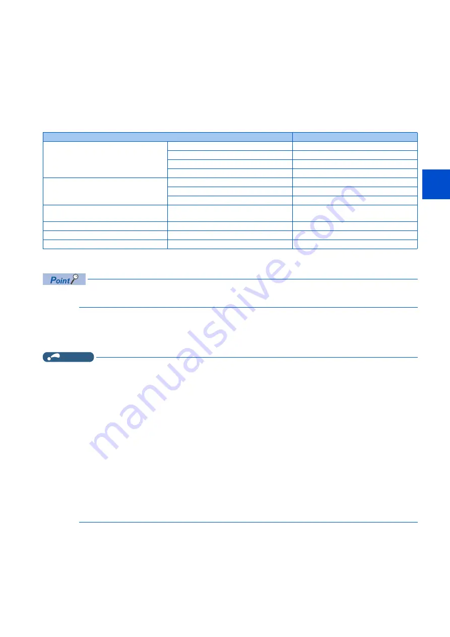
Motor
Pr.71 setting
Mitsubishi Electric standard efficiency motor
Mitsubishi Electric high-efficiency motor
SF-JR
0 (3)
SF-JR 4P 1.5 kW or lower
20 (23)
SF-HR
40 (43)
Others
0 (3)
Mitsubishi Electric constant-torque motor
SF-JRCA 4P
10 (13)
SF-HRCA
50 (53)
Others (SF-JRC, etc.)
10 (13)
Mitsubishi Electric high-performance energy-
saving motor
SF-PR
70 (73)
Mitsubishi Electric geared motor
GM-[]
1800 (1803)
Other manufacturer's standard motor
—
0 (3)
Other manufacturer’s constant-torque motor
—
10 (13)
Содержание FR-E800
Страница 17: ...16 1 Introduction 1 3 Related manuals MEMO ...
Страница 51: ...50 2 Basic Operation 2 8 I O terminal function assignment MEMO ...
Страница 89: ...88 3 Parameters 3 4 Parameter list by function group number MEMO ...
Страница 135: ...134 5 Speed Control 5 9 Troubleshooting in the speed control MEMO ...
Страница 153: ...152 6 Torque Control 6 7 Troubleshooting in torque control MEMO ...
Страница 195: ...194 8 E Environment Setting Parameters 8 18 Current average value monitor signal MEMO ...
Страница 237: ...236 10 D Operation Command and Frequency Command 10 6 Operation by multi speed setting MEMO ...
Страница 339: ...338 13 T Multi Function Input Terminal Parameters 13 9 Start signal operation selection MEMO ...
Страница 455: ...454 16 G Control Parameters 16 13 Speed smoothing control MEMO ...
Страница 481: ...480 18 Appendix 18 4 Parameters functions and instruction codes under different control methods MEMO ...


