Section 7: Replacement Procedures
TG3 Series Service Manual
Page 7-25
7.16 REPLACING GAP SENSOR (cont’d)
8.
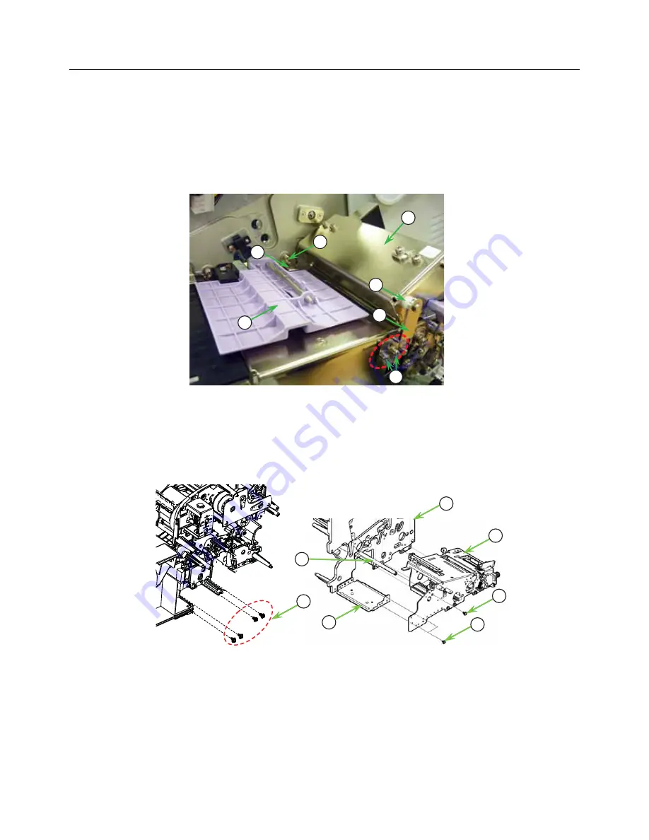
On top of the
Media route frame assembly
, press the tab of the purple
Pitch sensor guide
(6) and slide
it outwards.
9.
Remove a
screw
(7) of the
Media guide
(8) that clamped on the
Media route frame
assembly
(4) and
the
printer frame
.
10.
On the side of the
Lid Latch assembly
(9), unscrew two
screws
(10) to remove the
Plate (F/R position)
(11) that holds the
Lid Latch
. Remove the
plastic roller
(12) attached to the
shaft
and set side.
11.
Remove the
Media route frame assembly
(4) from the
printer frame
(13).
From the mechanism side of the printer, remove four
screws
(14) securing the
Media route frame
assembly
(4) to the
printer frame
(13).
From the
Media route frame
assembly
(4), remove two
screws
(15) attaching to the
Frame support A
(16) and then remove the
screw
(17) attaching to the
Shaft (support)
(18).
12.
Carefully disconnect the attached
wiring harnesses
, taking care not to cut off the cables as these are
very fine. Remove the
Media route frame assembly
from the
printer frame
.
12
7
6
8
10
11
9
13
4
16
14
15
17
18
Summary of Contents for TG308
Page 1: ...Service Manual For printer model TG3 Series www satoamerica com PN 9001226 A...
Page 6: ...Table of Contents Page iv TG3 Series Service Manual This page is intentionally left blank...
Page 7: ...Section 1 Introduction TG3 Series Service Manual Page 1 1 INTRODUCTION...
Page 251: ...Section 9 Sato Group of Companies TG3 Series Service Manual Page 9 1 SATO GROUP OF COMPANIES...


