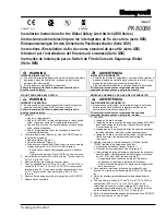
Installation Instructions for the
ISSUE 1
Hinge Mount Safety Limit Switch (GSS Series)
PK 80138
pending
Sensing and Control
IMPROPER INSTALLATION
•
Consult with local safety agencies and their
requirements when designing a machine-control
link, interface and all control elements that affect
safety.
•
Strictly adhere to all installation instructions.
Failure to comply with these instructions could
result in death or serious injury.
MOUNT, WIRE AND SEAL SWITCH
IMPROPER OPERATION
•
Ensure switch actuator achieves sufficient travel
for positive opening of normally closed (NC)
contacts to occur.
•
Do not use the device as a stop for the door.
Failure to comply with these instructions could
result in death or serious injury.
APPLIED POWER
•
During installation and functional testing, ensure
power is not applied to the machine.
Failure to comply with these instructions could
result in death or serious injury.
1.
Refer to:
•
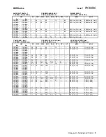
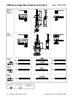
Pages 2 and 3 for EN 50047 wiring
configurations, specific travel distances for
each switch code (Ag=silver contacts,
Au=gold-plated contacts) and switch mounting
dimensions.
•
Page 4 for specifications.
2. Rotate switch head to desired position (90°
increments). Use the TORX
tamper-resistant
bit (included). Torque screws to 0,5 N m
(4.4 in lb).
3. Mount switch:
•
Ensure the operating lever pivot point and the
protective guard pivot points are as close to
each other as possible. Ensure the pin (not
included) fastened to the protective guard that
actuates the lever cannot become
disconnected from the lever.
•
Mount switch with lever using two M5 or #10
tamper-proof screws (not included). Torque
screws to mounting surface to
4,9 N m - 5,9 N m (43 in lb - 52 in lb).
4. Refer to circuit diagram on switch housing.
Diagram depicts safety switch in the “free
position” (protective guard closed). NC contacts
must be used for the safety circuit(s).
5. Remove tamper-proof screws on cover plate.
6. Connect stranded wire (0,75 mm
2
- 2,5 mm
2
,
18 AWG - 14 AWG) or solid wire (0,75 mm
2
-
1,5 mm
2
, 18 AWG - 16 AWG) to connector
terminals (use 90
°
C wire when ambient
temperature is over 75
°
C.):
•
Torque switch terminal screws to
0,8 N m - 1,0 N m (7 in lb - 9 in lb).
•
Torque ground screw to 0,8 N m - 1,0 N m
(7 in lb - 9 in lb) (GSC and GSE versions).
•
Torque connector to secure cable to switch
enclosure (if required) to 1,8 N m - 2,2 N m
(16 in lb - 19 in lb).
7.
GSE version only: Plug unused conduit entry(s)
(plugs included). Seal conduit opening according
to instructions in PK 80112.
8. Perform functional tests:
•
Open and close the protective guard several
times to ensure proper travel of the operating
lever.
•
Open the protective guard to ensure that the
NC contacts open.
9. Reassemble cover plate. Torque cover screws
0,5 N m (4.4 in lb).
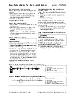
APPLICATION SUGGESTIONS
90
90
90
90
Summary of Contents for SYA14 Series
Page 2: ...2 107031 23 EN FR26 GLO 1199 Printed in France This page has been left intentionally blank ...
Page 6: ...6 107031 23 EN FR26 GLO 1199 Printed in France This page has been left intentionally blank ...
Page 26: ...26 107031 23 EN FR26 GLO 1199 Printed in France This page has been left intentionally blank ...
Page 62: ...62 107031 23 EN FR26 GLO 1199 Printed in France This page has been left intentionally blank ...
Page 70: ...70 107031 23 EN FR26 GLO 1199 Printed in France This page has been left intentionally blank ...
Page 76: ...76 107031 23 EN FR26 GLO 1199 Printed in France This page has been left intentionally blank ...
Page 78: ...78 107031 23 EN FR26 GLO 1199 Printed in France This page has been left intentionally blank ...
Page 79: ...107031 23 EN FR26 GLO 1199 Printed in France 79 8 CE Declaration of Conformity ...
Page 80: ...80 107031 23 EN FR26 GLO 1199 Printed in France This page has been left intentionally blank ...
Page 84: ......
Page 158: ......
Page 160: ......
Page 161: ...For application help call 1 800 537 6945 Honeywell MICRO SWITCH Sensing and Control 80 ...
Page 165: ...3 107022 14 EN FR26 GLO 0100 Printed in Germany This page has been left intentionally blank ...
Page 201: ...39 107022 14 EN FR26 GLO 0100 Printed in Germany This page has been left intentionally blank ...
Page 205: ...43 107022 14 EN FR26 GLO 0100 Printed in Germany This page has been left intentionally blank ...
Page 207: ...45 107022 14 EN FR26 GLO 0100 Printed in Germany This page has been left intentionally blank ...
Page 208: ...107022 14 EN FR26 GLO 0100 Printed in Germany 46 9 Declaration of Conformity ...
Page 219: ...11 107006 11 EN FR26 GLO 0300 Printed in Germany This page has been left intentionally blank ...
Page 229: ...21 107006 11 EN FR26 GLO 0300 Printed in Germany This page has been left intentionally blank ...
Page 257: ...49 107006 11 EN FR26 GLO 0300 Printed in Germany This page has been left intentionally blank ...
Page 260: ...107006 11 EN FR26 GLO 0300 Printed in Germany 52 9 3 Declaration of conformity ...
Page 340: ...Safety Perimeter Guarding Installation Manual FF SPS4 Series Safety Perimeter Guarding ...
Page 536: ...2 107004 15 EN FR26 ROW 0899 Printed in France This page has been left intentionally blank ...
Page 538: ...4 107004 15 EN FR26 ROW 0899 Printed in France This page has been left intentionally blank ...
Page 542: ...107004 15 EN FR26 ROW 0899 Printed in France 8 This page has been left intentionally blank ...
Page 620: ...86 107004 15 EN FR26 ROW 0899 Printed in France This page has been left intentionally blank ...
Page 624: ...90 107004 15 EN FR26 ROW 0899 Printed in France This page has been left intentionally blank ...
Page 626: ...92 107004 15 EN FR26 ROW 0899 Printed in France This page has been left intentionally blank ...
Page 627: ...107004 15 EN FR26 ROW 0899 Printed in France 93 8 CE Declaration of Conformity ...
Page 628: ...94 107004 15 EN FR26 ROW 0899 Printed in France This page has been left intentionally blank ...


