FF-SM Series Installation Manual
Connections and Setup
For application help: see Warranty Information
Honeywell
•
PK 107007-01 EN FR26 GLO 0298 Printed in France 33
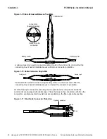
ST Connector with the Cable-to-cable Connector
1. Remove protective caps on the cable-to-cable connector and the optical fiber cable ends.
Keep the protective caps for future use.
2. Engage the ST fiber optic connector onto one side of the cable-to-cable connector. Turn
the ST connector until the cable-to-cable receptacle tabs are aligned with the ST
connector slots. Further engage the ST connector and turn it until secured.
Fiber Optic Cable Connection to the Connecting Box
CONNECTING BOX DAMAGE
•
Install one fiber optic cable per cable gland.
•
Properly install the sleeve tube into the cable gland and hand tighten the plastic cap screw
onto the cable gland to ensure proper cable sealing.
Failure to comply with these instructions will result in product damage.
1. Remove the plastic cap screw from the cable gland to gain access to the rubber seal
inside.
2. Remove the precut hole from the rubber seal.
3. Remove protective caps on the cable-to-cable connector and the optical fiber cable ends.
Keep the protective caps for future use.
4. Slide one ST connector of the fiber optic cable through the plastic cap screw and the
rubber seal inside the cable gland.
5. Repeat step 4 with the second ST connector.
6. Repeat steps 1 through 5 for all the safety mat optical cables as required.
7. Engage the ST fiber optic connector of mat 1 onto one side of the cable-to-cable
connector. Turn the ST connector until the cable-to-cable receptacle tabs are aligned with
the ST connector slots. Further engage the ST connector and turn it until secured.
8. Engage the ST fiber optic connector of mat 2 on the other side of the cable-to-cable
connector. Turn the ST connector until the cable-to-cable receptacle tabs are aligned with
the ST connector slots. Further engage the ST connector and turn it until secured.
9. Repeat steps 7 and 8 in order to have the safety mats optically connected in series.
10. Gently pull the 2 inch sleeve tube for all safety mat cables through the rubber seal of the
cable gland. Ensure the sleeve tube is visible from both sides of the cable gland.
11. Install the plastic cap screw onto the cable gland and hand tighten to ensure proper
sealing.
Summary of Contents for SYA14 Series
Page 2: ...2 107031 23 EN FR26 GLO 1199 Printed in France This page has been left intentionally blank ...
Page 6: ...6 107031 23 EN FR26 GLO 1199 Printed in France This page has been left intentionally blank ...
Page 26: ...26 107031 23 EN FR26 GLO 1199 Printed in France This page has been left intentionally blank ...
Page 62: ...62 107031 23 EN FR26 GLO 1199 Printed in France This page has been left intentionally blank ...
Page 70: ...70 107031 23 EN FR26 GLO 1199 Printed in France This page has been left intentionally blank ...
Page 76: ...76 107031 23 EN FR26 GLO 1199 Printed in France This page has been left intentionally blank ...
Page 78: ...78 107031 23 EN FR26 GLO 1199 Printed in France This page has been left intentionally blank ...
Page 79: ...107031 23 EN FR26 GLO 1199 Printed in France 79 8 CE Declaration of Conformity ...
Page 80: ...80 107031 23 EN FR26 GLO 1199 Printed in France This page has been left intentionally blank ...
Page 84: ......
Page 158: ......
Page 160: ......
Page 161: ...For application help call 1 800 537 6945 Honeywell MICRO SWITCH Sensing and Control 80 ...
Page 165: ...3 107022 14 EN FR26 GLO 0100 Printed in Germany This page has been left intentionally blank ...
Page 201: ...39 107022 14 EN FR26 GLO 0100 Printed in Germany This page has been left intentionally blank ...
Page 205: ...43 107022 14 EN FR26 GLO 0100 Printed in Germany This page has been left intentionally blank ...
Page 207: ...45 107022 14 EN FR26 GLO 0100 Printed in Germany This page has been left intentionally blank ...
Page 208: ...107022 14 EN FR26 GLO 0100 Printed in Germany 46 9 Declaration of Conformity ...
Page 219: ...11 107006 11 EN FR26 GLO 0300 Printed in Germany This page has been left intentionally blank ...
Page 229: ...21 107006 11 EN FR26 GLO 0300 Printed in Germany This page has been left intentionally blank ...
Page 257: ...49 107006 11 EN FR26 GLO 0300 Printed in Germany This page has been left intentionally blank ...
Page 260: ...107006 11 EN FR26 GLO 0300 Printed in Germany 52 9 3 Declaration of conformity ...
Page 340: ...Safety Perimeter Guarding Installation Manual FF SPS4 Series Safety Perimeter Guarding ...
Page 536: ...2 107004 15 EN FR26 ROW 0899 Printed in France This page has been left intentionally blank ...
Page 538: ...4 107004 15 EN FR26 ROW 0899 Printed in France This page has been left intentionally blank ...
Page 542: ...107004 15 EN FR26 ROW 0899 Printed in France 8 This page has been left intentionally blank ...
Page 620: ...86 107004 15 EN FR26 ROW 0899 Printed in France This page has been left intentionally blank ...
Page 624: ...90 107004 15 EN FR26 ROW 0899 Printed in France This page has been left intentionally blank ...
Page 626: ...92 107004 15 EN FR26 ROW 0899 Printed in France This page has been left intentionally blank ...
Page 627: ...107004 15 EN FR26 ROW 0899 Printed in France 93 8 CE Declaration of Conformity ...
Page 628: ...94 107004 15 EN FR26 ROW 0899 Printed in France This page has been left intentionally blank ...


