FF-SM Series Installation Manual
Connections and Setup
For application help: see Warranty Information
Honeywell
•
PK 107007-01 EN FR26 GLO 0298 Printed in France 39
Final Switching Device (FSD) Monitoring
Overview
Monitoring a machine control system requires two machine primary control elements. British
Standards define an element as an “…electrically powered element which directly controls the
machine’s normal operating motion in such a way that it is last (in time) to operate when
motion is initiated or arrested.” (BS 6491: Part 1 (2.8): 1984). Element types vary based on
the method of arresting the hazardous motion. If the element is a relay, it must be a captive
(positive-guided) contact type. The secondary control element is defined as “a machine
control element independent of the machine primary control element(s) and capable of
removing the source of power from the prime mover of the relevant dangerous parts in an
emergency.” (BS 6491: Part 1 (2.9): 1984)
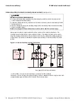
Final switching device monitoring allows the control circuitry to regularly and automatically
check the external safety relays K1 and K2 (connected to the equipment outputs) after each
activation of the safety mat. See figure 3-5. After deactivation of the mat sensor, the control
unit will automatically restart and the safety outputs (normally open contacts) will close. If
safety relays K1 and K2 are operating correctly, the activation of the restart push button will
first energize safety relay K3 and then the final switching devices K1 and K2. After release of
the push button, the safety relay K3 will de-energize allowing the next machine operation.
Figure 3-5 Final Switching Device (FSD) Monitoring Connection
NO P/B
K1
K2
K3
(1)
K3
OR
Single channel
machine control circuit
Phase
(DC+)
Neutral
(DC-)
Dual channel
machine control circuit
(recommended circuit)
Phase
(DC+)
Neutral
(DC-)
Fuse
K1
K2
K3
Fuse
K1
K2
K3
Fuse
K1
K2
K3
K1
K3
K3
K2
Phase
(DC+)
Neutral
(DC-)
NO P/B
K1
K2
K3
Fuse
(1)
K3
(1)
K2
FSD
(1)
K1
FSD
FF-SM
control unit
B2
C4
B3
B1
C2
Optional test
input
(or jumpered)
C1
internal
fuse
A4
A5
OR
Single channel
machine control circuit
Phase
(DC+)
Neutral
(DC-)
Dual channel
machine control circuit
(recommended circuit)
Phase
(DC+)
Neutral
(DC-)
Fuse
K1
K2
K3
Fuse
K1
K2
K3
Fuse
K1
K2
K3
Signalling
(relay status)
A2
A1
(1) : RC (220
Ω
+ 0,22
µ
F) for AC interfaces or varistors for DC interfaces
See page 42 for full size schematic.
Summary of Contents for SYA14 Series
Page 2: ...2 107031 23 EN FR26 GLO 1199 Printed in France This page has been left intentionally blank ...
Page 6: ...6 107031 23 EN FR26 GLO 1199 Printed in France This page has been left intentionally blank ...
Page 26: ...26 107031 23 EN FR26 GLO 1199 Printed in France This page has been left intentionally blank ...
Page 62: ...62 107031 23 EN FR26 GLO 1199 Printed in France This page has been left intentionally blank ...
Page 70: ...70 107031 23 EN FR26 GLO 1199 Printed in France This page has been left intentionally blank ...
Page 76: ...76 107031 23 EN FR26 GLO 1199 Printed in France This page has been left intentionally blank ...
Page 78: ...78 107031 23 EN FR26 GLO 1199 Printed in France This page has been left intentionally blank ...
Page 79: ...107031 23 EN FR26 GLO 1199 Printed in France 79 8 CE Declaration of Conformity ...
Page 80: ...80 107031 23 EN FR26 GLO 1199 Printed in France This page has been left intentionally blank ...
Page 84: ......
Page 158: ......
Page 160: ......
Page 161: ...For application help call 1 800 537 6945 Honeywell MICRO SWITCH Sensing and Control 80 ...
Page 165: ...3 107022 14 EN FR26 GLO 0100 Printed in Germany This page has been left intentionally blank ...
Page 201: ...39 107022 14 EN FR26 GLO 0100 Printed in Germany This page has been left intentionally blank ...
Page 205: ...43 107022 14 EN FR26 GLO 0100 Printed in Germany This page has been left intentionally blank ...
Page 207: ...45 107022 14 EN FR26 GLO 0100 Printed in Germany This page has been left intentionally blank ...
Page 208: ...107022 14 EN FR26 GLO 0100 Printed in Germany 46 9 Declaration of Conformity ...
Page 219: ...11 107006 11 EN FR26 GLO 0300 Printed in Germany This page has been left intentionally blank ...
Page 229: ...21 107006 11 EN FR26 GLO 0300 Printed in Germany This page has been left intentionally blank ...
Page 257: ...49 107006 11 EN FR26 GLO 0300 Printed in Germany This page has been left intentionally blank ...
Page 260: ...107006 11 EN FR26 GLO 0300 Printed in Germany 52 9 3 Declaration of conformity ...
Page 340: ...Safety Perimeter Guarding Installation Manual FF SPS4 Series Safety Perimeter Guarding ...
Page 536: ...2 107004 15 EN FR26 ROW 0899 Printed in France This page has been left intentionally blank ...
Page 538: ...4 107004 15 EN FR26 ROW 0899 Printed in France This page has been left intentionally blank ...
Page 542: ...107004 15 EN FR26 ROW 0899 Printed in France 8 This page has been left intentionally blank ...
Page 620: ...86 107004 15 EN FR26 ROW 0899 Printed in France This page has been left intentionally blank ...
Page 624: ...90 107004 15 EN FR26 ROW 0899 Printed in France This page has been left intentionally blank ...
Page 626: ...92 107004 15 EN FR26 ROW 0899 Printed in France This page has been left intentionally blank ...
Page 627: ...107004 15 EN FR26 ROW 0899 Printed in France 93 8 CE Declaration of Conformity ...
Page 628: ...94 107004 15 EN FR26 ROW 0899 Printed in France This page has been left intentionally blank ...


