107031-23 EN FR26 GLO 1199 Printed in France
31
3.3.2.1
Sample Calculation
(Point-of-operation guarding)
Country: USA
Application: Mechanical/hydraulic power press
Protection: Point-of-operation guarding
Formula: S >V(t
1
+t
2
)+C
−
V = 63 in./sec.
−
t
1
= 14.5 ms (FF-SYA30080C2)
−
t
2
= 200 ms (machine stop time; including
response time of all interconnecting
components, such as relays, solenoids,
brakes, etc.)
−
C = 3.08 in. (ANSI B11.1 and ANSI B11.2)
[FF-SYA30]
S = 63 (0.014 + 0.200) + 3.08 in. = 16.56 in.
3.3.2.2
Sample Calculation
(Perimeter guarding)
Country: USA
Application: Robotics
Protection: Perimeter guarding
Formula: S >V(t
1
+t
2
)+C
−
V = 63 in./sec.
−
t
1
= 15 ms (FF-SYA60096C2)
−
t
2
= 200 ms (robotics stop time, including
response time of all interconnecting
components, such as relays, solenoids,
brakes, etc.)
C = 33.46 in. (USA)
S = 63 (0.015 + 0.200) + 33.46 = 47.00 in.
3.4
How to Calculate Minimum Distance Considering
Reflective Surfaces
REFLECTIVE SURFACES
•
To prevent two optical paths to the receiver, install FF-SYA light curtains so there are
no reflective surfaces within the beam angles of the emitter and receiver.
•
Calculate reflective minimum distance using formula D= L(tan 2.5
°
), where
−
D is the minimum distance to reflective surface (always greater than 131 mm or 5.16 in)
−
L is the installed scanning range
Failure to comply with these instructions could result in death or serious injury.
Reflective surfaces near the sensing field can cause reflection of the sensing beams and
result in two optical paths to the receiver. The light curtain must be installed so there are
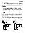
no reflective surfaces within the beam angles of the emitter and receiver. Figure 3-2
illustrates the beam angles.
Calculate the reflective minimum distance using the following formula:
D = 131 mm, for scanning distances bewteen 0 and 3 m
D = L x tan 2.5
°
, for scanning distances greater than 3 m
D = Minimum distance to reflective surface (always greater than 131 mm or 5.16 in.)
L = Installed scanning range
The emitter and receiver must have the same protected height and resolution. The
emitter and receiver must be mounted at the same height and aligned with each other.
Summary of Contents for SYA14 Series
Page 2: ...2 107031 23 EN FR26 GLO 1199 Printed in France This page has been left intentionally blank ...
Page 6: ...6 107031 23 EN FR26 GLO 1199 Printed in France This page has been left intentionally blank ...
Page 26: ...26 107031 23 EN FR26 GLO 1199 Printed in France This page has been left intentionally blank ...
Page 62: ...62 107031 23 EN FR26 GLO 1199 Printed in France This page has been left intentionally blank ...
Page 70: ...70 107031 23 EN FR26 GLO 1199 Printed in France This page has been left intentionally blank ...
Page 76: ...76 107031 23 EN FR26 GLO 1199 Printed in France This page has been left intentionally blank ...
Page 78: ...78 107031 23 EN FR26 GLO 1199 Printed in France This page has been left intentionally blank ...
Page 79: ...107031 23 EN FR26 GLO 1199 Printed in France 79 8 CE Declaration of Conformity ...
Page 80: ...80 107031 23 EN FR26 GLO 1199 Printed in France This page has been left intentionally blank ...
Page 84: ......
Page 158: ......
Page 160: ......
Page 161: ...For application help call 1 800 537 6945 Honeywell MICRO SWITCH Sensing and Control 80 ...
Page 165: ...3 107022 14 EN FR26 GLO 0100 Printed in Germany This page has been left intentionally blank ...
Page 201: ...39 107022 14 EN FR26 GLO 0100 Printed in Germany This page has been left intentionally blank ...
Page 205: ...43 107022 14 EN FR26 GLO 0100 Printed in Germany This page has been left intentionally blank ...
Page 207: ...45 107022 14 EN FR26 GLO 0100 Printed in Germany This page has been left intentionally blank ...
Page 208: ...107022 14 EN FR26 GLO 0100 Printed in Germany 46 9 Declaration of Conformity ...
Page 219: ...11 107006 11 EN FR26 GLO 0300 Printed in Germany This page has been left intentionally blank ...
Page 229: ...21 107006 11 EN FR26 GLO 0300 Printed in Germany This page has been left intentionally blank ...
Page 257: ...49 107006 11 EN FR26 GLO 0300 Printed in Germany This page has been left intentionally blank ...
Page 260: ...107006 11 EN FR26 GLO 0300 Printed in Germany 52 9 3 Declaration of conformity ...
Page 340: ...Safety Perimeter Guarding Installation Manual FF SPS4 Series Safety Perimeter Guarding ...
Page 536: ...2 107004 15 EN FR26 ROW 0899 Printed in France This page has been left intentionally blank ...
Page 538: ...4 107004 15 EN FR26 ROW 0899 Printed in France This page has been left intentionally blank ...
Page 542: ...107004 15 EN FR26 ROW 0899 Printed in France 8 This page has been left intentionally blank ...
Page 620: ...86 107004 15 EN FR26 ROW 0899 Printed in France This page has been left intentionally blank ...
Page 624: ...90 107004 15 EN FR26 ROW 0899 Printed in France This page has been left intentionally blank ...
Page 626: ...92 107004 15 EN FR26 ROW 0899 Printed in France This page has been left intentionally blank ...
Page 627: ...107004 15 EN FR26 ROW 0899 Printed in France 93 8 CE Declaration of Conformity ...
Page 628: ...94 107004 15 EN FR26 ROW 0899 Printed in France This page has been left intentionally blank ...


